AT-OMNI-121 / AT-OMNI-122
37
IR Control
Atlona has tested and verified the following components for this application. However, other components may also
be used. Note that
IR control is only supported on
RS-232 2
port (bottom set of connectors) of the OmniStream
encoder and decoder.
•
Xantech 789-44 4-Source Connecting Block
•
Xantech 12 V PSU
•
IR Receiver (Atlona AT-IR-CS-RX)
•
IR Emitter (Atlona AT-OMNI-IR-TX)
1.
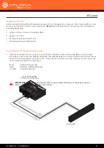
Unscrew the captive screw connectors on the Xantech 789-44 4-Source Connecting Block, using a regular
screwdriver, and connect the SIGNAL, GROUND, and POWER leads of the AT-IR-CS-RX to the Xantech 789-44
4-Source Connecting Block, as shown below. The presence or absence of white markings on each wire of the
AT-IR-CS-RX will denote the signal type:
IR IN
= Dashed dark gray line
GND
= Solid (no marking) black wire
+12 VDC = solid dark gray line
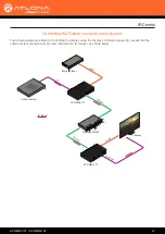
Connecting the IR Receiver to the Encoder
EMITTERS
IR IN
STA
TUS
GND
+12 VDC
IR
RCVR
12VDC
789-44
CONNECTING BLOCK
Xantech 789-44PSRP
4-Source Connecting Block
AT-IR-CS-RX
Signal
Power
Ground
Required Equipment
IMPORTANT:
When connecting the IR emitter to the encoder, the IR lens of the emitter must be
within 1” of the IR window on the source device.

