


8 Chapter 2 Installation and Wiring
Series 230 Automatic Transfer Switch C2000 Intelligent Controller User Manual
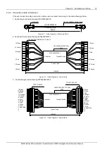
2.1.3 Controller Wiring
Use the grounding cable LTSC2000SLW03 provided with the C2000 Controller to connect the grounding port located
on the side of the Controller and the grounding port on the cabinet.
Grounding Screw on Controller
Figure 2-4 Grounding Port on C2000 Controller
WARNING
!
!
!
!
Grounding is very important in order to protect the automatic transfer switch (switch and controller) from electrical disturbances,
lightning, electromagnetic disturbances, etc.
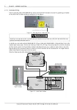
Locate the two connection cables 230S400SLW01-1 (Power Cable) and 230S400SLW01-2 (Signal Cable) found in the
transfer switch accessories. First connect the Power Cable to the X1 Power Connectors located on both the Controller
and the transfer switch. The Power Cable is labled to identify which end goes in which connector. Next, connect the
Signal Cable to the X2 Driver Connectors located on both the Controller and the transfer switch. The Signal Cable is
labled to identify which end goes in which connector.
Refer the following connection diagram for more details, Fig 2-5.
Controller
Transfer
Switch
X2
Transfer Switch
Signal Connector
Transfer Switch
Power Connector
1
14
X2
Signal
Connector
X4
User Connector
X1
Power
Connector
X1
Power
Connector
X2
Signal
Connector
1
11
1
6
66
6
X3
User
Connector
Figure 2-5 Inputs/Output Interface
Содержание 230 Series
Страница 2: ......
Страница 4: ......
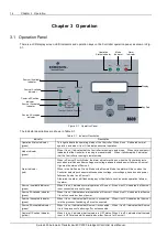
Страница 22: ...18 Chapter 3 Operation Series 230 Automatic Transfer Switch C2000 Intelligent Controller User Manual ...


