


AT32WB415
Series Reference Manual
2022.04.13
Page 165
Ver 2.00
Each timer (TMR2 to TMR5) consists of a 16-bit prescaler, which is used to generate the CK_CNT that
enables the counter to count. The frequency division relationship between the CK_CNT and TMR_CLK
can be adjusted by setting the value of the TMRx_DIV register. The prescaler value can be modified at
any time, but it takes effect only when the next overflow event occurs.
Table 14-2 TMRx internal trigger connection
Slave timer
IS0
(STIS = 000)
IS1
(STIS = 001)
IS2
(STIS = 010)
IS3
(STIS = 011)
TMR2
TMR1
USB_SOF
-
TMR4
-
TMR1
TMR2
TMR5
TMR4
TMR4
TMR1
TMR2
-
-
TMR5
TMR2
-
TMR4
-
Note 1: If there is no corresponding timer in a device, the corresponding trigger signal ISx is not present.
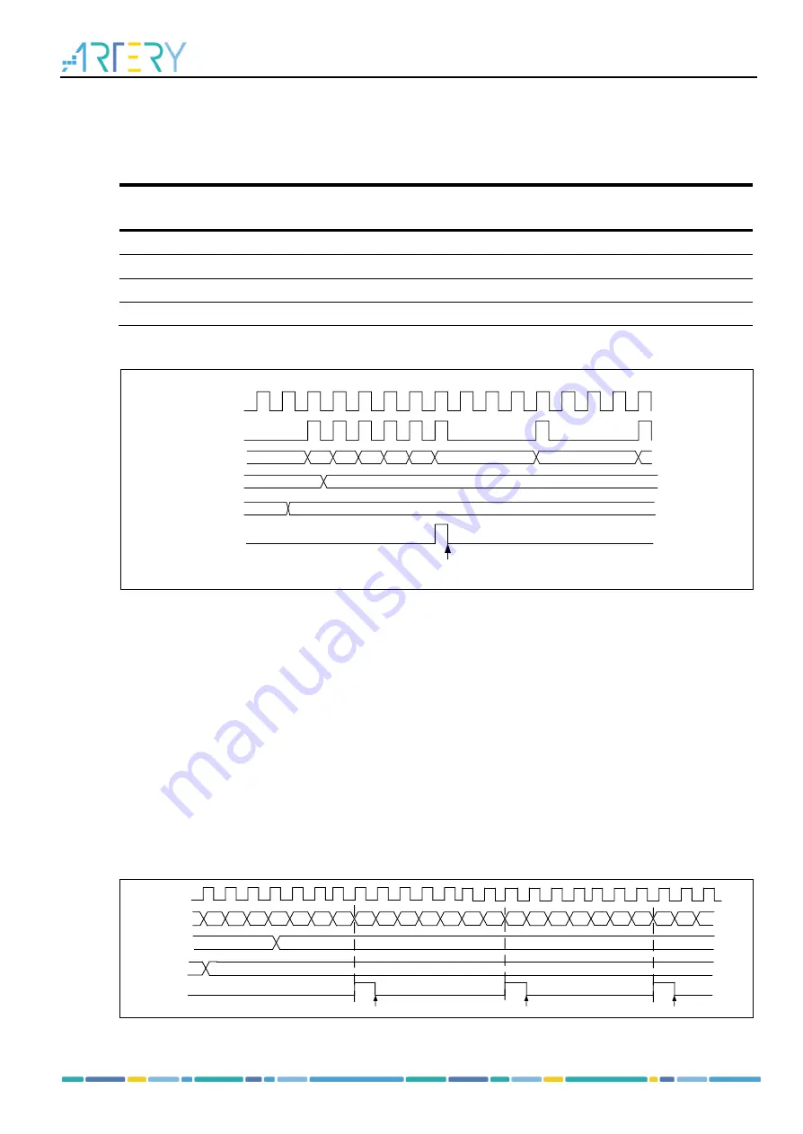
Figure 14-7 Counter timing with prescaler value changing from 1 to 4
TMR_CLK
CK_CNT
COUNTER
OVFIF
DIV[15
:
0]
18
17
19
1A
1B
1C
0
3
00
01
Clear
PR[15
:
0]
1C
14.1.3.2 Counting mode
The timer (TMR2 to TMR5) supports several counting modes to meet different application scenarios.
Each timer has an internal 16-bit up, down, up/down counter. TMR2/5 can be extended to 32-bit by
setting the PMEN bit. The TMRx_PR register is loaded with the counter value. The value in the
TMRx_PR is immediately moved to the shadow register by deault. When the periodic buffer is enabled
(PRBEN=1), the value in the TMRx_PR register is transferred to the shadow register only at an overflow
event. The OVFEN and OVFS bits are used to configure the overflow event.
Settng the TMREN bit (TMREN=1) enables the timer to start counting. Base on synchronization logic,
however, the actual enable signal TMR_EN is set 1 clock cycle after the TMREN is set.
Upcounting mode
In upcounting mode, the counter counts from 0 to the value programmed in the TMRx_PR register,
restarts from 0, and generates a counter overflow event, with the OVFIF bit being set. If the overflow
event is disabled, the register is no longer reloaded with the preload and re-loaded value after counter
overflow occurs, otherwise, the prescaler and re-loaded value will be updated at an overflow event.
Figure 14-8 Overflow event when PRBEN=0
0
1
2
3
...
31
32
0
1
2
3
...
31
32
0
1
2
3
COUNTER
31
32
0
1
32
...
PR[15:0]
OVFIF
TMR_CLK
0
DIV[15:0]
22
Clear
Clear
Clear


