background image

Accessories

98

Содержание ARRIFLEX 435 ES

Страница 1: ...ON CD ROM DISKS OR INTERNET SITES OR USED IN THEIR ENTIRE FORM OR IN EXCERPTS WITHOUT OUR PREVIOUS WRITTEN AGREEMENT IF YOU ARE DOWNLOADING PDF FILES FROM OUR INTERNET HOME PAGE FOR YOUR PERSONAL USE...

Страница 2: ...ocking grip on camera door 120m magazine eyepiece lock display RUN button operation control indicator MODE button SEL button PHASE button SET button PROG button sliding switch DISPLAY LOCK sliding swi...

Страница 3: ...tensioning plate compartment for TC buffer battery functional expansion module FEM mechanical footage indicator overload display RS socket video optical tap...

Страница 4: ...locking key for manual image compensation unlocking key for finder arm grip system hook for tape focus power supply socket 11 pin accessory socket overload display for 11 pin accessory socket functio...

Страница 5: ...without a lens or a protective cap in the lens mount receptacle Never operate the movement locking mechanism while the camera is running Ensure that the camera is stabily positioned Remove the batter...

Страница 6: ...to the ARRIFLEX 435 as well as to the ARRIFLEX 435ES model Sections that only apply to one model are indi cated as such in the heading Explanation of the Symbols in the Instruction Manual photo indic...

Страница 7: ...p System 15 Operation from the Shoulder 17 3 Power Supply 19 Battery NC 24 7 R 20 Charger NCL 24 R 20 CHS 1 Camera Highspeed Supply Module 21 Mains Unit NG 12 24 R 21 Mains Unit NG 12 26 R 22 Accessor...

Страница 8: ...t RCU 1 95 Laptop Camera Controller LCC 96 Accessory Socket Distributor 11 pin 97 R S Socket Distributor 3 pin 97 10 Super 35 99 Converting the Lens Mount Receptacle to Super 35 99 Converting the Brid...

Страница 9: ...claws and registration pins The angle of the mirror shutter can be adjusted mechanically from 11 2 to 180 in fixed stops on the ARRIFLEX 435 when the camera is not running The electronic mirror shutte...

Страница 10: ...Introduction 10 magazine opening cover movement in locked position loop protector...

Страница 11: ...ly with an appropriate screwdriver not with the commonly used coin 2 Installation of the Camera Packing and Transport In order to prevent damage to the mirror shutter a protective cap must be on the l...

Страница 12: ...balancing of the camera on the tripod and mounting of accessories The BP 8 is designed for 19 mm support rods the BP 9 for 15 mm support rods The bridge plates consist of the base plate photo the sli...

Страница 13: ...pin photo snaps back audibly The camera s position can then be fixed with the clamp lever Slide the support rods into the guides and clamp Equip the camera with the required accessories to determine...

Страница 14: ...e support rods from above and let it click into place by applying slight pressure push the LS 8 onto the support rods from the front Slide the relevant support ring photo onto the lens but do not tigh...

Страница 15: ...tem in various positions as required A safety mechanism in the handgrip prevents automatic loosening This mechanism is activated by screwing in the handgrips tightly Before screwing in the handgrips m...

Страница 16: ...Installation 16 shoulder set S 4 shoulder cushion base plate...

Страница 17: ...Plates BP 8 BP 9 The mounting screws on the shoulder set must first be screwed back as far as they will go photo Now slide the shoulder set from the rear into the dovetail guide on the bridge plate a...

Страница 18: ...he camera with the index pin and fasten it to the camera with the mounting screw Check that the shoulder cushion is firmly seated on the camera Operation from the Shoulder without the Shoulder Set The...

Страница 19: ...able voltage range is from 20 6 to 35 V DC Depending on the desired frame rate the following voltage range should be chosen for the power supply Frame Rate Range Voltage 1 130 fps 20 6 35 V DC 130 150...

Страница 20: ...or the spiral battery cable KC 29S into the power supply socket on the camera and into the battery socket Note If the battery voltage is not sufficient for the chosen frame rate the bat symbol will s...

Страница 21: ...below 20 V are indicated for each battery by a LOW BAT LED next to the respective input socket of the CHS 1 To prevent over discharging the module switches off if either battery voltage drops below 1...

Страница 22: ...e mains unit to 26 V Plug the battery cable KC 20S or the spiral battery cable KC 29S into the power supply socket on the camera and into the 26 V socket on the mains unit Note The NG 12 24 R can easi...

Страница 23: ...that the accessories to be used are suited to the available voltage 24 V accessories are normally attached to the RS socket photo At 24 V the available continuous current is 3 A maximum the peak load...

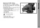
Страница 24: ...Power Supply 24...

Страница 25: ...age of the magazine or the camera Time code can only be recorded with the new ARRIMAG magazines The ARRIMAG magazines and the ARRIFLEX III magazines are automatically recognized For the ARRIFLEX 35 II...

Страница 26: ...e loading process considerably The ARRI Film Cutting Gauge photo simplifies cutting in the darkroom The following steps should be carried out in a darkroom or film changing bag Remove the loop protect...

Страница 27: ...Insert the film through the left slit on the magazine throat assembly from the inside photo Do not catch the film With your free hand turn the drive gear counter clockwise while carefully pushing the...

Страница 28: ...ure that the take up shaft catch engages the slot on the plastic core Press down the hinged locking clip on the take up shaft Hang the head of the film into the film core and bend over photo The bent...

Страница 29: ...l they lock in place Flip up the hinged locking clip on the take up shaft Pull the film roll upwards and off Note When pulling the film roll off the shaft grip it from underneath as far as possible to...

Страница 30: ...he loop protector photo attached to avoid damage to the film stock and the magazine throat assembly If the ARRIFLEX 435 435ES is transported without a maga zine it is recommended to attach the magazin...

Страница 31: ...utter locks in the following positions 11 2 22 5 30 45 60 75 90 105 120 135 144 172 8 and 180 Setting the Mirror Shutter Angle By briefly depressing the PHASE button the mirror shutter is positioned t...

Страница 32: ...reached Turn the locking mechanism photo towards the LOCK position until this locks in place The adjusting mechanism may possibly have to be turned slightly back and forth By gently twisting the shut...

Страница 33: ...er Angle Measurement Holding the PHASE button depressed in standby will make the camera inch forward The display shows the measured shutter angle in the upper line The lower line displays the voltage...

Страница 34: ...ning as well as in standby Note The electronically adjustable mirror shutter is also equipped with an adjustment mechanism that allows mechanical adjustment The electronic mirror shutter function mus...

Страница 35: ...e camera 11 2 22 5 30 45 60 75 90 105 120 135 144 172 8 and 180 With accessories such as the LCC CCU or RCU 1 other shutter angles can be set The procedure is described in the respective instruction m...

Страница 36: ...the shutter angle must now be adjusted and locked manually See the section Mechanically Ad justable Mirror Shutter Note As a warning that the electronic shutter has been switched off the angle symbol...

Страница 37: ...t on the supply frequency To achieve constant exposure the camera s frame rate the supply frequency of the lighting and the angle of the mirror shutter must all relate to each other As the camera fram...

Страница 38: ...r surface Using the included special forceps pull the ground glass photo out of the holder by its tongue photo Check that the ground glass to be inserted as well as the ground glass frame are complete...

Страница 39: ...block Turn the movement locking lever photo towards the OPEN position to swing the movement block away from the film gate Press the film gate locking lever photo towards the ma gazine throat assembly...

Страница 40: ...dirt Take hold of the film gate by the filter holder and place onto the film gate shaft from above Check that the film gate is correctly seated on the shaft Press the film gate locking lever towards t...

Страница 41: ...filters can be inserted into the filter holder The camera display does not show a warning when a filter is in use Switch off the camera s main switch and disconnect the camera from the power supply be...

Страница 42: ...ng Removing the Spacer Gate Press the safety spring photo downwards at the same time pressing the spacer gate backwards by its handle photo Then remove by pulling upwards Installing the Spacer Gate Ta...

Страница 43: ...the film does not get caught between the magazine and the dovetail on the camera opening Position the back part of the magazine s throat assembly on the lower dovetail of the camera opening With your...

Страница 44: ...ne is firmly seated With your right hand pull the film loop downwards out of the camera photo Then push it as far upwards as possible until the loop can be positioned between the movement plate and th...

Страница 45: ...position in relation to the image will also not be guaranteed Close the camera door Note Threading the movement is described and displayed on the inside of the camera door marking for film loop positi...

Страница 46: ...film stock used differs from this perforation distance the movement can be optimally adapted using the pitch adjustment mechanism It is recommended to establish the optimal pitch setting for the film...

Страница 47: ...magazine throat assembly photo Ensure that the loop does not get twisted behind the movement block as otherwise the film could be damaged when removing the magazine Swing the movement block forwards...

Страница 48: ...Camera Body 48...

Страница 49: ...he bayonet ring photo counter clockwise as far as it will go and then pulling out the protective cap Never put your fingers into the lens mount receptacle Push the lens into the lens mount receptacle...

Страница 50: ...viewfinder system For colour video cameras a beamsplitter with a ratio of 50 50 is also available and can be fitted by a service center The entire viewfinder system can be replaced by a video finder...

Страница 51: ...Attaching the Eyepiece Ensure that the knurled ring is turned to the OPEN position Position the eyepiece on the viewfinder Turn the knurled ring photo towards the LOCK position Check that the eyepiec...

Страница 52: ...e swivelled approx 270 left to right On the left side of the camera the viewfinder arm locks into the horizontal position The viewfinder arm friction can be altered if necessary by turning the Allen s...

Страница 53: ...s in two positions 180 apart This allows the image compensation to be set to provide an upright image when using a finder extension If the viewfinder image is inverted without the finder exten sion th...

Страница 54: ...Pull the warning display module off sideways Attach the ARRIGLOW module straight Attaching at an angle could damage the plug Push on the ARRIGLOW module photo Screw both fastening screws tight Adjusti...

Страница 55: ...rds the rear until it locks in place securely Exchanging the Viewfinder System The entire viewfinder system can be replaced by a 100 video finder See Chapter 9 Accessories Removing the Viewfinder Syst...

Страница 56: ...Optics 56...

Страница 57: ...oto is located on the back of the camera below the magazine opening First switch on the mains unit if used Connect the camera to the mains unit or to the battery Switch on the main camera switch In th...

Страница 58: ...n control indicator photo glows red Once the set frame rate has been reached the operation control indicator turns green Stopping the Camera Again depress the RUN button photo briefly While the camera...

Страница 59: ...isplay will show the OFF sign Note Locking the PHASE button has no influence on the inching function Locking the SEL and SET buttons has no influence on accessories such as the RCU 1 Inching Inching c...

Страница 60: ...or Power supply voltage V Configuration of the film counter take counter m ft Unit of measurement m ft Mode 4 Time Code time hours minutes Time Code time seconds frames Time Code on off Time Code tim...

Страница 61: ...am cannot be run with the set values e g incorrect magazine for the frame rate set in the program or battery voltage too low for the frame rate set in the program Symbol Meaning blinks Only on ARRIFLE...

Страница 62: ...ectly locked the camera is not operational Display Warning of Reverse Opera tion with an ARRIFLEX 35 III 300 m Magazine Reverse operation is not possible with an ARRIFLEX 35 III 300 m magazine If the...

Страница 63: ...3 by depressing the MODE button twice Depress the SEL button twice the first digit in the upper display line blinks Within three seconds depress the SET button The currently set counting value of Mode...

Страница 64: ...he SEL button repeatedly until the upper display line blinks The SET button switches between film counter and shutter angle Frame Rates The ARRIFLEX 435 435ES offers the possibility to set and store t...

Страница 65: ...n repeatedly until the desired value is reached Repeat this procedure until all digits are set to the desired values For frame rates below 100 fps a 0 should be entered as the first digit for frame ra...

Страница 66: ...between the standard frame rate NORM and the pro grammed frame rate PS CCU while the camera is running Note The attached magazine must be suited for the programmed frame rate For HS operation above 13...

Страница 67: ...camera has run up until the horizontal bar is no longer visible in the viewfinder The frame rate will increase by 0 2 fps while the button is de pressed Displaying the Power Supply Voltage Mode 3 Chan...

Страница 68: ...ings Depressing the MODE button confirms the selection and changes the display back to Mode 1 Setting the Volume of the Warning Signal Change from Mode 1 to Mode 6 by depressing the MODE button five t...

Страница 69: ...out manually The white balance is set to standard values for interior and exterior lighting situations The inte grated image storage technology enables viewing of a stored image or the alternation bet...

Страница 70: ...ring Remove the cover Attach the video optic The index pin photo on the viewfinder system defines the correct position Tighten the retaining ring by hand Note The video optic is tilted upwards by 5 Re...

Страница 71: ...e video camera Screw the video camera photo onto the C mount thread on the video optic Mounting the Anti Flicker Processor AFP 2 Screw the dovetail adapter photo onto the grip system of the ARRIFLEX 4...

Страница 72: ...anti flicker function can be optimized by adjusting the slit screw PHASE ADJ Adjusting the Video Optic Adjusting the Image Position Loosen the clamping ring photo approx 15 as seen in the direction of...

Страница 73: ...of the video optic can be shifted with the gear photo on the video camera clamping ring adjustment screw vertical position adjustment screw horizontal position focus adjustment ring clamp for focus ad...

Страница 74: ...Video Assist Saystem 74...

Страница 75: ...ter or in a rental house To switch over the viewfinder image turn the switching knob photo The knob does not need to be unlocked All other operating elements are identical in function to those on the...

Страница 76: ...with an Allen key until the viewfinder image is free of distortion Retighten the Allen screws Using the AVF 2 on the Right Side of the Camera The AVF 2 can also be locked into horizontal position on t...

Страница 77: ...an be also fitted to the video viewfinder Mounting the Video Viewfinder Removing the Standard Viewfinder System Lock the viewfinder arm into horizontal position Unscrew the three fastening screws of t...

Страница 78: ...light into the dovetail guide and clamp Connect the plug to the RS socket photo By adjusting the flexible arm bring the work light into the desired position The work light can be turned on and off wi...

Страница 79: ...ther with cable KC 26S to the 11 pin accessory socket or with cable KC 42S to the RS socket Set the heating level with the toggle switch photo LO low heat output HI higher heat output If the camera an...

Страница 80: ...e Use of the RU 1 is possible but not recommended The range of frame rates that can be adjusted with the RU 1 is limited to 8 1 130 fps Furthermore the set frame rate does not correspond to the scale...

Страница 81: ...s synchronization of the camera to other equipment such as TV monitors By means of a BNC socket it is possible to synchronize to an external standard video signal 50 60 Hz or through an inductive pick...

Страница 82: ...435ES Checking all set operational parameters Entry of programmed frame rate changes programs Entry of programmed shutter angle changes programs only 435ES Display and operation of the film counter S...

Страница 83: ...ff the main camera switch position OFF Plug the cable KC 24S 2 4m or KC 30S 20m into the socket on the side photo of the camera control unit pressing the slide on the plug in the direction of the plug...

Страница 84: ...RIFLEX 435 the menu SHUTTER 2 has no function The SPEED Menu With the SPEED menu any frame rate within the acceptable range can be set from 1 to 99 999 fps in increments of 0 001 fps above 100 fps in...

Страница 85: ...rame rates within the acceptable range can be fine tuned from 1 to 99 999 fps in increments of 0 001 fps above 100 fps in increments of 0 01 fps This can be done in standby or while the camera is runn...

Страница 86: ...entered directly Depress key 9 VAR in the SHUTTER menu Enter the desired shutter angle If the digit after the decimal point is to have the value 0 this needs not be entered Complete the input with the...

Страница 87: ...e input by depressing the ENTER key all unfilled digits will default to zero Transfer the new TC time to the camera with the SEND key Changing Time Code User Bits Depress key 2 USERBITS is displayed a...

Страница 88: ...with the SEND key The OPTIONS Menu The OPTIONS menu allows access to the sub menus ASYNC MODE LENGTH UNIT END WARNING and COUNTER DISPLAY MODE Note The menu point END WARNING is not available on the...

Страница 89: ...are exceeded the CCU 1 will show an error reading when the selected values are sent to the camera General information The FETCH key transfers a program that is already stored in the camera to the sele...

Страница 90: ...ENTER key Confirm the displayed shutter angle value should be bet ween 11 2 and 180 with the ENTER key This value will not be transferred to the camera as the mirror shutter of the ARRIFLEX 435 is no...

Страница 91: ...ame rate If the digits after the decimal point need not be entered complete the entry with the ENTER key Enter the desired starting shutter angle If the digit after the decimal point needs not be ente...

Страница 92: ...with the ENTER key Enter the desired end frame rate If the digits after the decimal point need not be entered complete the entry with the ENTER key Note A maximum of four aperture stops can be com pe...

Страница 93: ...s not affect connected accessories such as the CCU 1 Note The program itself is stored in the camera and therefore can also be activated if the CCU is not plugged in As soon as a program is activated...

Страница 94: ...35 435ES Select the desired menu point with keys 1 to 2 Switch on or off the acoustic signal with key 4 STATUS STATUS displays the values currently set on the camera COUNTER COUNTER displays the curre...

Страница 95: ...tomatic exposure compensation Complete programs can easily be created to control changing of frame rate and angle of the mirror shutter over a certain period of time These programs can be recalled rep...

Страница 96: ...d user bits Additionally the LCC can be used to log film stock and to create camera reports Monitoring Controlling Frame rate and shutter angle can be precisely controlled Often used values can be sto...

Страница 97: ...the right side a RUN button is also integrated into the R S socket distributor Mounting the R S Socket Distributor Plug the R S socket distributor into the R S socket photo Tightenthefasteningscrew ph...

Страница 98: ...Accessories 98...

Страница 99: ...t be altered for the format This ensures that the lenses and accessories are exactly aligned to the displaced optical center of Super 35 Converting the Lens Mount Receptacle to Super 35 For shooting i...

Страница 100: ...35 as follows Removethetwoscrews photo Turn the compensation bar 180 and screw tightly in this position Note The viewfinder system is so designed that no alteration is necessary for shooting in Super...

Страница 101: ...time code only the new magazines ARRIMAG may be used on the ARRIFLEX 435 With the ARRIFLEX 35 III or 35 II magazines no time code can be recorded Time Code Frame Rates Recording time code is only poss...

Страница 102: ...the movement block and damage the film guides Unscrewbothfasteningscrews photo Remove the film recognition module photo in the direction of the movement block When installing the module make certain t...

Страница 103: ...position will not have the correct relation to the image Set the knurled knob photo to LOADING POSITION The upper film loop must lie within the marking photo Note For instructions on setting the loop...

Страница 104: ...Kodak 5231 B W Neg 8 Kodak 5239 Color Rev 6 Kodak 5240 Color Rev 5 Kodak 5245 Color Neg 7 Kodak 5247 Color Neg 6 Kodak 5248 Color Neg 7 Kodak 5293 Color Neg 6 Kodak 5294 Color Neg 5 Kodak 5296 Color N...

Страница 105: ...and the next digit blinks Depress the SET button repeatedly until the desired value appears Confirm the entry with the SEL button Displaying the TCS Value Mode 6 Depress the MODE button five times to...

Страница 106: ...ng the ENTER key all unfilled digits will default to zero Transfer the new TC time to the camera with the SEND key Depress the EXIT key to return to the main menu Changing Time Code User Bits with the...

Страница 107: ...e necessary If the time code cable with the correct LTC signal is connected to the CCU or ACC socket time code time and user bits will automatically be taken on by the camera Synchronization can be ch...

Страница 108: ...om Mode 1 to Mode 4 Time code time will be displayed with Hours Minutes in the first line and Seconds Frames in the second line of the camera display Displaying Time Code User Bits Mode 5 Depress the...

Страница 109: ...en if no valid time code is set In this case the acoustic TC warning TC switched on but not set will sound see TC Warnings at the end of this chapter It is possible to record a test time code with a n...

Страница 110: ...code and ESU operation the counting of the images and of time code can run apart if the source of synchronization does not run at an exact time code rate This can cause a jump in the time code count T...

Страница 111: ...fer battery is located in a compartment on the side of the functional expansion module Switch off the camera s main switch and disconnect the camera from the power supply Completely unscrew the two fa...

Страница 112: ...lay the acoustic warning can be suppressed for 15 minutes The acoustic TC warning is automatically switched off as long as the camera is running After stopping the camera the warning tone will begin t...

Страница 113: ...splay Digit for TC Warnings Warning Remedy 8 hours since TC last set reset TC as last setting was over 8 hours ago TCS value not valid reset TCS value given ESU frame rate check given ESU frame rate o...

Страница 114: ...module TC not buffered reset TC either the TC buffer battery is used up or the power supply was insufficient or interrupted or over 10 hours passed since TC was last set 3rd Display Digit for TC Warni...

Страница 115: ...t free cloths and swabs Also suitable are special cleaning tissues and small sponges as used in cleaning com puters and video equipment When cleaning the film movement do not exert too much pressure U...

Страница 116: ...to a layer of emulsion forming on the film gate This can cause scratches on the film and can also lead to a change in the film s coefficient of friction The film gate must be removed for cleaning Atte...

Страница 117: ...off the camera s main switch and disconnect the camera from the power supply before removing the film gate Turn the knurled knob photo on the movement until its marking matches that on the movement b...

Страница 118: ...r gate backwards by its handle photo Then remove by pulling upwards Remove the layer of emulsion from the spacer gate photo with a plastic rod e g an ARRI film gate cleaner Under no circumstances use...

Страница 119: ...ds with a screw driver Pull the field lens photo out off the holder by its tongue photo using the special forceps Clean the field lens with a dry lint free cloth Make sure that the frame is completely...

Страница 120: ...hroat assembly cover back in place Replace the holder plate for the loop protector and re tighten the throat assembly cover with the three screws Setting Friction on the ARRIMAG 120 Swing both roller...

Страница 121: ...switch and disconnect the camera from the power supply Place the special key photo in the holes of the friction adjustment and turn in steps The adjustment must lock in at each step When setting frict...

Страница 122: ...Maintenance 122...

Страница 123: ...ile the camera is running the display will show a warning after the camera is stopped The operation control indicator will remain red the camera cannot be re started and must be checked by an ARRI ser...

Страница 124: ...m gate Carefully clean film gate and magazine throat or or film running surfaces in the magazine throat if defective replace Scratches on the glossy side of the negative In the image area Dirty or dam...

Страница 125: ...in the film gate area Clean film gate area film edge is not straight use different film stock Pressure exposures Mechanical stress Pressure exposures do not effect arround perforation holes on the per...

Страница 126: ...h Capacity or voltage of the battery Check the battery charge following the directions the selected frame rate is insufficient in the instruction manual Check that the camera movement turns easily by...

Страница 127: ...mount positive locking Convertible for Super 35 Flange Focal Distance 51 98 0 01mm Mirror Shutter ARRIFLEX 435 Can be adjusted mechanically from 11 2 180 and locks in the following positions 11 2 22 5...

Страница 128: ...ge 20 6 35 V DC Function Monitoring Power supply voltage BAT Synchronous running ASY Time code recording TC Display of time code information Time Code The time code generator that is integrated into t...

Страница 129: ...ods 240mm 15mm K2 21958 0 Support rods 340mm 19mm K2 47347 0 Support rods 340mm 15mm K2 47348 0 Power Supply Battery NC 24 7 R K2 41950 0 HS supply module CHS 1 K2 52002 0 Battery cable KC 20S K2 4196...

Страница 130: ...7088 0 Extra handgrip K4 46680 0 Camera control unit CCU 1 with cable K2 42320 0 External synchronization unit ESU 1 K2 46006 0 Remote switch RS 4 K2 46942 0 Remote control unit RCU 1 K2 47197 0 Work...

Страница 131: ...remote run switch RS 4 79 video viewfinder VT 2 77 work light WL 3 78 accessory power supply 22 accessory socket 11 pin 22 RS socket 23 accessory socket distributor 11 pin 97 acoustic war ning settin...

Страница 132: ...lacing 111 buttons MODE 59 86 PHASE 59 64 67 86 93 PROG 59 86 93 RUN 58 60 SEL 59 93 SET 59 86 93 C C mount 71 cable KC 20S 20 21 22 KC 24S 83 KC 29S 20 21 22 KC 30S 83 KC 34 72 KC 36 72 KC 37 72 KC 2...

Страница 133: ...changing 87 TIMECODE menu 87 user bits changing 87 camera report 96 CC code correct 107 CCU socket 80 107 109 CCU 1 82 changing bag 26 charger NCL 24 R 20 CHS 1 19 21 CID discharge lamps 37 continuous...

Страница 134: ...on 92 automatic 95 external standard video signal 81 external synchronization unit ESU 1 80 81 110 external time code synchr onization 107 eyecup 79 eyepiece 51 adjusting friction 52 adjusting the dio...

Страница 135: ...friction eyepiece 52 viewfinder arm 52 friction of ARRIMAG 120 adjusting 120 function monitoring 128 functional expansion module FEM 80 interfaces 80 fuses 123 G gelatine filters 41 GEN LOCK input 69...

Страница 136: ...ses 49 attaching 49 lens support LS 7 14 lens support LS 8 14 support 14 LOCK sliding switch 59 93 loop protector 11 26 30 loose film loops in the magazine 123 LTC 80 bit 109 LTC output 109 LTC signal...

Страница 137: ...60 63 64 65 configuring ARRIFLEX 435ES 64 Mode 2 60 65 66 Mode 3 60 63 67 Mode 4 60 108 109 Mode 5 60 108 Mode 6 60 68 105 110 Mode 7 60 MODE button 59 86 movement 42 display movement open 62 pitch ad...

Страница 138: ...ARRIFLEX 435ES 91 RCU 1 80 95 remote control unit RCU 1 80 95 remote run switch RS 4 79 reverse operation 66 RS 232 interface 80 RS 4 79 RU 1 80 RUN button 58 60 97 additional on right side 97 S S 4...

Страница 139: ...29S 20 21 22 spirit level 12 standard frame rates 64 selecting 65 standard video signal exter nal 81 standard viewfinder system removing 77 standby 57 starting 58 stopping 58 Super 35 99 converting br...

Страница 140: ...ting 72 image position of video optic adjusting 72 mounting 70 loop length checking 103 LTC output 109 LTC signal 107 output 109 quartz accuracy 128 recording switching off 109 recording switching on...

Страница 141: ...ece 52 viewfinder friction 52 viewfinder system 50 128 adjusting 52 attaching 55 displays in viewfinder 50 exchanging 55 removing 55 voltage of TC buf fer battery 110 voltage range 19 128 VT 2 77 W wa...

Страница 142: ...33 99 E mail service arrican com Germany Arnold Richter Cine Technik T rkenstra e 89 D 80799 M nchen phone 089 3809 0 fax 089 3809 1244 fax service 089 3809 1793 E mail service KDenk arri de USA ARRI...

Страница 143: ...Appendix 143 Technical data are subject to change without notice Printed in Germany Ident Nr 09 91924 0...

Отзывы: