


16
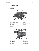
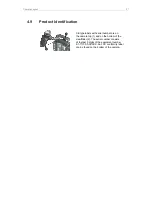
Camera Layout
TC I/O (BNC)
The TC connector is a BNC socket. It accepts and distributes LTC
(Longitudinal Time Code) signals.
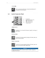
4.3
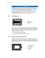
Audio Connector Panel
1
2
3
4
5
6
1
Protective Caps
2
Headphone Out & Volume Control
3
IN A
XLR 5-pin Audio Input
4
IN B
XLR 3-pin Audio Input
5
IN C
XLR 3-pin Audio Input
6
Input Signal Selector
Headphone Out
Headphone 3.5 mm stereo TRS (“Mini-jack”) output for monitoring au-
dio channels.
IN A (5-pin XLR)
XLR input for microphone signals (including 48V phantom power sup-
ply) and line level signals.
IN B & C (3-pin XLR)
XLR input for microphone signals (including 48V phantom power sup-
ply), line level signals and AES3 digital signals.
NOTICE
Rubber caps protect the XLR connectors from dirt and moisture. Always cap
unused XLR connectors.