15
Tensor
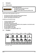
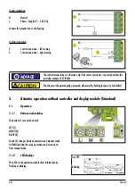
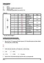
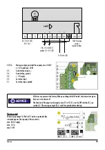
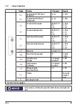
Connection configuration
Use only shielded wires
18
GND Poti
19
Output Poti 0...100% (Wiper, output impedance 1 kΩ)
20
+Ub Poti 5...24 V DC
56, 57
Fault message output (potential free closer max. 200 V/0.5 A)
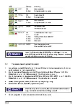
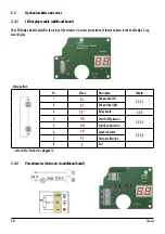
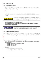
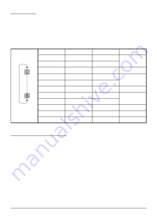
Menu pattern
Nr.
Menu
Description
Chapter
1
El
End position left
7.2.2.1
2
Et
End position right
3
tE
*
Relay board
5.3.3
4
PL
Poti left
5.3.2
5
Pt
Poti right
6
Ao
Message output
7.2.2.4
7
Hb
Switch-off hysteresis
7.2.2.5
8
Hd
Switch-on hysteresis
9
tP
Speed reduction
7.2.2.6
10
Ft
Firmware Revision
11
E
Exit
* only visible, if module is plugged in
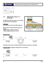
Actual value output of the potentiometer end positions
The actual value output must be set for both end positions.
•
Choose menu item „PL“ for programming of the left end position or „PR“ for the right end position and confirm with button
[M]. The display shows a confirmation dialog.
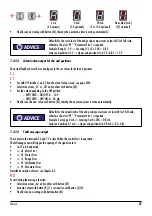
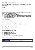
PL
Pt
•
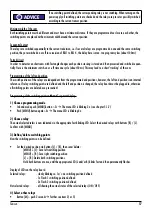
Set the desired value via button [R] or [L]. The display shows a confirmation dialog.
L_
.
0%
Ln
.
90%
Lu
.
10%
L_
.
100%
L
≡.
free values
•
Finally save the new value with button [M], hereby the next menu item is activated automatically.
Содержание TENSOR
Страница 1: ...Original declaration of incorporation with manual for ARIS actuator Tensor TE1512DE01 Stellantriebe ...
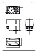
Страница 6: ...6 Tensor 3 3 Dimensions F05 Ø50 F03 Ø36 50 65 M6x9 M6x9 M5x9 25 25 60 63 86 153 Tensor S ...
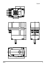
Страница 7: ...7 Tensor M6x11 M6x11 F05 Ø50 50 65 25 25 153 86 40 60 63 82 Tensor M ...
Страница 31: ......

