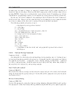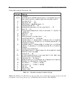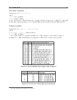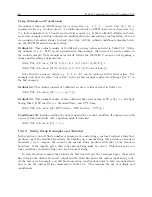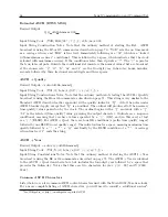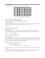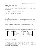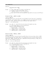
56
Timing, IRIG-B and Pulses
8.4.6
Wire Losses
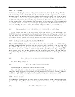
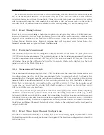
Another factor affecting the available voltage is the resistive losses through the cabling. Wire has a
certain resistivity associated with it that is determined by its metallic composition, and resistance
determined by the diameter and length. For example, single-strand, 22 AWG (bare, enamel-coated)
copper wire has a resistance of approximately 19.6 ohms per 1000 feet. To compute the loss we
must include both wires in the connection, signal and return. For coaxial cabling, the resistance of
the center conductor is rated differently than the shield. For a twisted pair, both of them should
essentially have the same resistance per cut length. Using 500 feet of 22 AWG shielded twisted pair
wire, and including the source resistor, the available voltage would be as calculated in 8.3:
(8.3)
V pp available
= 4
.
5
−
I
×
19
.
6 (
R
source
)
−
I
×
19
.
6 (
R
wire
) = 0
.
58
V pp
So, you can see that most of the drive voltage is lost with 100 mA of current and 500 feet of
22 AWG twisted pair transmission line; this includes the voltage losses at the source resistor. 0.58
Vpp may not be detected by the decoder in some IED’s.
To assure reliable detection, make your
cable runs as short as possible, use a larger diameter wire and carefully distribute the loads.
8.4.7
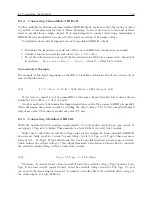
Voltage Matching for Modulated IRIG-B
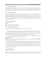
With modulated IRIG-B, it was mentioned that certain decoders are very intolerant of drive voltage
variation. If the IED specification says that the acceptable voltage range is 3.3 Vpp
±
0.5 volt, and
the available voltage is high, then you must reduce the voltage using a dropping resistor (
R
drop
).
The value of the dropping resistor is determined by dividing the difference voltage (
V
dif f
) by the
device current (
I
dev
). For example, suppose that the available voltage is 4.3 Vpp, the (nominal)
acceptable voltage is 3.3 Vpp, and the device current is 10 mA. Determine the dropping resistor
value.
(8.4)
R
drop
=
V
dif f
÷
I
dev
= (4
.
3
−
3
.
3)
÷
0
.
01 = 100
.
4
Ohms
The Power dissipation (P) is:
(8.5)
P
=
I
2
R
= 0
.
01
2
×
100
.
4 = 0
.
01
W atts
In this example, an eighth-watt resistor should work fine.
For a voltage that is too low, then the modulated IRIG-B signal level must be increased by
some other means, such as (1) distributing the load differently to reduce the current (raising the
available voltage), (2) by reducing the loss through the wiring, or (3) by using an amplifier.
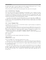
8.4.8
Cable Delays
Electromagnetic waves travel at the speed of light (C) in free space or vacuum and a fraction of that
speed through cabling. The speed of an electromagnetic wave in free space is given by Constant 8.6.
(8.6)
C
≈
9
.
82
×
10
8
f eet/second
Содержание 1092A
Страница 4: ...iv ...
Страница 18: ...xviii LIST OF TABLES ...
Страница 129: ...C 10 Option 20A Four Fiber Optic Outputs 111 Figure C 7 Option 20A Jumper Locations ...
Страница 131: ...C 11 Option 27 8 Channel High Drive 113 Figure C 8 Option 27 Jumper Locations ...
Страница 148: ...130 Options List Figure C 10 Option 29 Connector Signal Locations ...

