Chapter 5
Setting Internal Jumpers
5.1
Introduction
Jumpers in the the 1092A/B/C and 1093A/B/C series clocks are normally set up at the factory
according default settings, or according to the purchase order if requested. If it should be necessary
to change any jumpers or to enable an alternate function, follow the instructions in this chapter.
5.2
Cover Removal
To change jumper configurations, the instrument cover must be removed. Remove top cover as
follows:
1. On all Models, disconnect the power cord. If equipped with Option 04 (power switch), first
turn the power switch to OFF.
2. Using a T-25 driver, remove the four screws securing the cover (and rack-mount ears, if used).
Lift the cover off.
5.3
Main Board Version
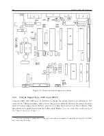
Figure 5.1 indicates important jumper and test point locations on the main board in the Model
1092A/B/C and 1093A/B/C. Use this drawing to assist you with locating the jumpers you may
want to configure. Jumpers are noted on the main board with a “JMP” prefix before the numbered
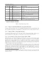
location. For example, jumper 3 would have a label of JMP3 on the main board. Table 5.1 lists all
of the current jumpers and their functions.
Содержание 1092A
Страница 4: ...iv ...
Страница 18: ...xviii LIST OF TABLES ...
Страница 129: ...C 10 Option 20A Four Fiber Optic Outputs 111 Figure C 7 Option 20A Jumper Locations ...
Страница 131: ...C 11 Option 27 8 Channel High Drive 113 Figure C 8 Option 27 Jumper Locations ...
Страница 148: ...130 Options List Figure C 10 Option 29 Connector Signal Locations ...

