


2
Unpacking the Clock
1.3
Unpacking and Locating Accessories
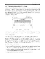
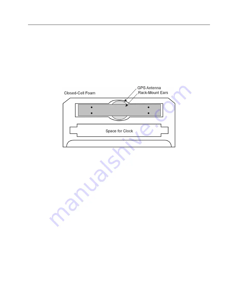
The Model 1093A/B/C, and included accessories, are packed between two closed-cell foam shells
(see Figure 1.1). The Model 1092A/B/C series clocks are packed between layers of molded foam
pieces.
Carefully pull apart the two shells to extract the clock and accessories.
Some of the
accessories (i.e. antenna and rack-mount ears) are located in one of these shells for protection.
In the diagram below, you can see how the GPS antenna and rack-mount ears are located in the
closed-cell foam marked with the label that reads,
ADDITIONAL PARTS INSIDE
Figure 1.1: Packaging of Accessories
Antenna cable, clock and operation manual are located between the two pieces of closed-cell
foam.
The rack-mount ears and antenna are embedded in the packing foam side labeled
ADDI-
TIONAL PARTS INSIDE.
1.4
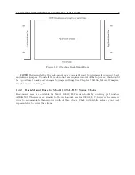
Attaching Rack-Mount Ears to 1093A/B/C Series Clocks
Each Model 1093A/B/C comes with two rack-mount ears suitable for mounting in a 19-inch system
rack. These ears have four mounting holes, two of which are used to attach them to the sides of
the clock. Since it is required to remove the M25 x 10 mm screws which attach the cover to the
chassis, it may be good to attach the ears after first making any jumper configuration inside the
clock.
You will want to return to this section after making these changes.
1.4.1
Mounting Instructions
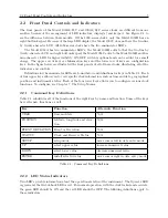
1. Using a Torx T25 driver or large slot screwdriver, remove the four M5x10 screws attaching
the clock cover to the chassis. Use either a T25 or large slot screwdriver.
2. With the ear facing out from the front panel, match the lower set of holes of the ear to the
cover/chassis and remount the M5x10 screws.
3. Repeat this procedure with the other side of the chassis and other ear.
Содержание 1092A
Страница 4: ...iv ...
Страница 18: ...xviii LIST OF TABLES ...
Страница 129: ...C 10 Option 20A Four Fiber Optic Outputs 111 Figure C 7 Option 20A Jumper Locations ...
Страница 131: ...C 11 Option 27 8 Channel High Drive 113 Figure C 8 Option 27 Jumper Locations ...
Страница 148: ...130 Options List Figure C 10 Option 29 Connector Signal Locations ...