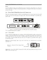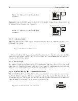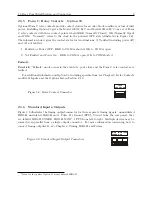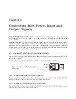
2.3 Rear Panel Identification and Connectors
9
2.3.5
Form C, Relay Contacts – Option 93
Optional Form C relay contacts provide contact closure for an out-of-lock condition, or loss of inlet
power. Installing Option 93 gives the Model 1092A/B/C and Model 1093A/B/C one set of Form
C relay contacts with three contact points labeled ERR (Normally Closed), OK (Normally Open)
and COM; “Normally” refers to the clock in the powered OFF state (illustrated in Figure 2.8).
The information below gives the contact states for two situations: (1) faulted (including power off)
and, (2) not faulted.
1. Faulted, or Power OFF – ERR to COM is shorted, OK to COM is open.
2. Not Faulted and Power On – ERR to COM is open, OK to COM shorted.
Failsafe
Essentially “Failsafe” mode occurs in the event of a power loss, and the Form C relay contacts are
faulted.
For additional information on Option 93, including specifications, see Chapter 9, Relay Contacts
and Event Inputs and the Options List in Section C.19.
Figure 2.8: Relay Contact Connector
LOCK
ERR OK COM
2.3.6
Standard Inputs/Outputs
Figure 2.9 illustrates the timing output connector for three separate timing signals: unmodulated
IRIG-B, modulated IRIG-B and 1 Pulse Per Second (PPS). Viewed from the rear panel, they
are labeled IRIG-B UNMOD, IRIG-B MOD
, 1 PPS from left to right. Multiple devices may be
connected in parallel from a single output connector. For more information concerning how to
connect timing outputsv11, see Chapter 8, Timing, IRIG-B and Pulses.
Figure 2.9: Standard Input/Output Connectors
IRIG-B IRIG-B 1PPS
UNMOD MOD
1
Main board requires Option 92 for modulated IRIG-B.
Содержание 1092A
Страница 4: ...iv ...
Страница 18: ...xviii LIST OF TABLES ...
Страница 129: ...C 10 Option 20A Four Fiber Optic Outputs 111 Figure C 7 Option 20A Jumper Locations ...
Страница 131: ...C 11 Option 27 8 Channel High Drive 113 Figure C 8 Option 27 Jumper Locations ...
Страница 148: ...130 Options List Figure C 10 Option 29 Connector Signal Locations ...

