Chapter 8
Timing, IRIG-B and Pulses
8.1
Introduction
This section covers some basic information about timing signals and how to connect them to your
IEDs. Common questions concerning connecting timing signals include:
•
What are the different types of IRIG-B, and what are the differences?
•
How do you connect multiple devices to one timing output?
•
How far can you transmit timing signals?
•
What kind of cabling and connectors should I use?
The steps involved in getting your devices synchronized to the GPS are fairly simple and should
not take long to complete. To expedite the process, make sure to:
1. determine the type of timing signal each piece of equipment requires, and
2. enable the equipment to receive the timing signal
Various methods are used to configure equipment to receive IRIG-B time codes including setting
a physical jumper, or using a setup application. Some equipment can auto detect the timing signal,
so that nothing else is required, other than connecting the cable.
8.2
Timing Output Description
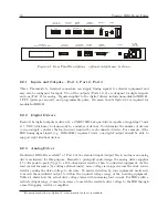
When viewing the rear panels of the Model 1092A/B/C and 1093A/B/C, you will see a number
of different types of connectors as illustrated in Figure 8.1.
Generally, there is a power inlet
connector, a GPS antenna connector, two DB-9 serial connectors (one is an optional RS-232 port),
one optional SPDT relay connector, one optional and two standard timing outputs. The Model
1093A/B/C series clocks also have an option plate that can be replaced by one of several accessory
boards. Whereas the Model 1093A/B/C has an internal power supply, the Model 1092A/B/C
clocks have a separate external power supply.
Содержание 1092A
Страница 4: ...iv ...
Страница 18: ...xviii LIST OF TABLES ...
Страница 129: ...C 10 Option 20A Four Fiber Optic Outputs 111 Figure C 7 Option 20A Jumper Locations ...
Страница 131: ...C 11 Option 27 8 Channel High Drive 113 Figure C 8 Option 27 Jumper Locations ...
Страница 148: ...130 Options List Figure C 10 Option 29 Connector Signal Locations ...

