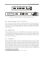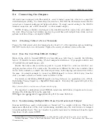
8.4 Connecting the Outputs
55
8.4.4
Connecting Unmodulated IRIG-B
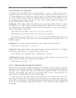
To drive multiple loads from one unmodulated IRIG-B output, make sure that the loads are wired
in parallel. A common term for this is “Daisy-Chaining”, however the idea is to drive all of these
loads in parallel from a single output. It is much simpler to connect loads using unmodulated
IRIG-B than for modulated, because all of the loads are driven at the same voltage.
To determine load current imposed on one Unmodulated IRIG-B output:
1. Determine the impedance or resistance (
R
dev
) of each IED load (check device manuals).
2. Calculate the load current for each device (
I
dev
= 5
V
÷
R
dev
).
3. To get the total current, sum up all the load currents for all devices connected to the output
in question.
I
devT
=
I
dev
1
+
I
dev
2
+
. . .
+
I
devN
,
where T = Total for N devices.
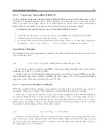
Unmodulated Example
For example, if the input impedance of the IED is 5 kilohms, determine the device current (I) as
seen in Calculation 8.1:
(8.1)
I
=
V
÷
R
dev
= 5
V olts
÷
5000
Ohms
= 0
.
001
Amps
(1
mA
)
If you were to connect ten of the same IED’s to the same output, then the total current drawn
would be 10 x 0.001 A = 0.01 A (10 mA).
Another method is to determine the lumped impedance of all of the connected IED’s in parallel.
Then, determine the overall current by dividing the drive voltage (5 V) by the computed lumped
impedance value. This current should not exceed 75 mA.
8.4.5
Connecting Modulated IRIG-B
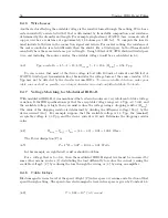
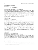
While the modulated driver supplies approximately 4.5 volts peak-to-peak (Vpp) open circuit, it
can supply 3 Vpp into 50 ohms. This amounts to about 0.064 A (64 mA) drive current.
Make sure to check the acceptable voltage range for the equipment. Some modulated IRIG-B
decoders are fairly sensitive to peak-to-peak voltage levels (3.3 Vpp
±
0.5 Vpp), others are more
tolerant (0.1 – 10 Vpp). With added loads, the clock’s modulated driver produces more current,
which reduces the output voltage at the output terminals. Calculation 8.2 shows how to calculate
the available output voltage with a 10 mA drive current.
(8.2)
V pp
= 4
.
5
V pp
−
I
×
19
.
6
Ohms
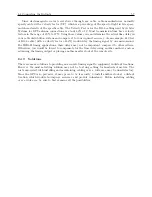
Therefore, if you had 10 mA of load current (I load) the available voltage (Vpp) would be 4.304
Vpp. If the load current equals 100 mA, then the available voltage would be 2.54 Vpp. So, you
can see how the increasing load current (i.e number of loads) affects the available drive voltage at
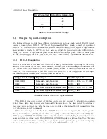
the clock output. See also Table 8.1.
Содержание 1092A
Страница 4: ...iv ...
Страница 18: ...xviii LIST OF TABLES ...
Страница 129: ...C 10 Option 20A Four Fiber Optic Outputs 111 Figure C 7 Option 20A Jumper Locations ...
Страница 131: ...C 11 Option 27 8 Channel High Drive 113 Figure C 8 Option 27 Jumper Locations ...
Страница 148: ...130 Options List Figure C 10 Option 29 Connector Signal Locations ...

