60
Relay Contacts and Event Inputs
9.2.6
Firmware Setup
Reconfiguration of the firmware may also be required to allow measurement and display of Event
Time Data and/or 1 PPS Deviation. See Figure 7.17 for detail on configuring the Event/Deviation
parameters from the front panel. See Section 10.2.4 for details on using the RS-232 interface.
9.2.7
Displaying Data
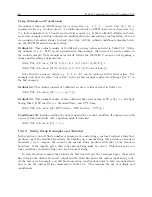
Event and deviation data can be accessed from either the front panel or via RS-232 com-
mands. The following paragraphs describe the steps required to access data using the front panel
EVENT/DEVIATION key. When pressing the EVENT/DEVIATION key, the display will enter a
circular scroll, which begins by showing the data (if any is present) for Channel A, as previously
configured for Event Recording in Section 10.2.4. The readout will display one of the event times
using the following format:
CH A EVENT #nnn TIME
ddd:hh:mm:ss.sssssss
Where:
nnn = event number (001 to 400)
ddd = day of year of the event (1 to 366)
hh = hour of the event (00 to 23)
mm = minute of the event (00 to 59)
ss.sssssss = second and fractional seconds of the event (e.g. 59.9999999)
Pressing the UP and DOWN keys will scroll the display through all events presently stored in
the event time buffer. If the event display mode is exited and then re-entered, the first event data
displayed for a given channel will correspond to the same event number as was last displayed for
that channel. However, the data itself may be changed if it has been overwritten.
To clear the event buffer, press the EVENT/DEVIATION key again, while viewing event data.
This will cause the display to issue the following prompt:
CLEAR EVENT (A)?
NOTE:
If the event capture channel is not configured for event time recording, the CLEAR EVENT
prompt will not be displayed.
Clocks display the CLEAR EVENT prompt only if the event capture channel was previously
configured for event time recording. Press ENTER during this display to delete all of the records
in the event buffer, and to allow recording of new event times, starting with event number 001.
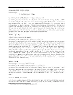
If the event capture channel is configured for 1–PPS Deviation (via Event/Deviation Setup
Menu), the readout will display the deviation of the 1–PPS input signal. In this case, the readout
display will have the format:
A 1 PPS XXXXX.XX ?S
SIGMA: XXXXX.XX ?S
Where: The top number is the mean (average) value of the most recent 16 records in the event
buffer, and represents the mean deviation (in microseconds) of the measured 1–PPS signal from
Содержание 1092A
Страница 4: ...iv ...
Страница 18: ...xviii LIST OF TABLES ...
Страница 129: ...C 10 Option 20A Four Fiber Optic Outputs 111 Figure C 7 Option 20A Jumper Locations ...
Страница 131: ...C 11 Option 27 8 Channel High Drive 113 Figure C 8 Option 27 Jumper Locations ...
Страница 148: ...130 Options List Figure C 10 Option 29 Connector Signal Locations ...

