3.2 Option 08, 10 to 60 VDC Terminal Power Strip
11
No.
Country
Specification
Rating
P01
Continental Europe
CEE 7/7
220V
P02
Australia, NZ, PRC
AS3112-1981
240V
P03
U.K.
BS 1363
240V
P04
Denmark
Afsnit 107-2-01
240V
P05
India
BS 546
220V
P06
Israel
SI 32
220V
P07
Italy
CEI 23-16/VII 1971
220V
P08
Switzerland
SEV 1011.1959
220V
P09
North America and ROC
NEMA 5-15P CSA C22.2#42
120V
P10
Japan
JIS8303
120V
Table 3.1: Available IEC-320 Cordsets by Country
3.2
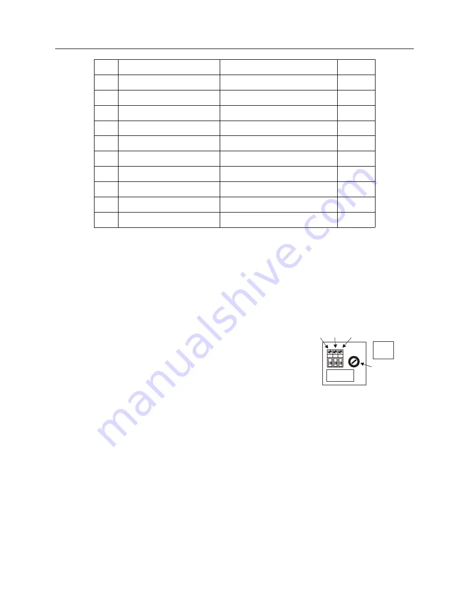
Option 08, 10 to 60 VDC Terminal Power Strip
This option replaces the standard power supply with one accepting 10 to 60 VDC (only),
<
20 VA
typical. Replaces the standard IEC-320 inlet with a 3-pole terminal strip. Provides input surge
protection (SWC) for compliance with ANSI C37.90-1 and IEC 801-4. Option 08 operates from
common low-voltage battery systems, including 12, 24, and 48 VDC.
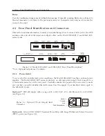
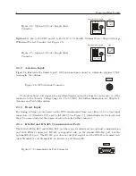
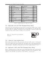
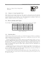
Figure 3.2: Option 08 Power Supply Inlet
Description
G – +
FUSE 1AT/250V
10 – 60 Vdc
DC ONLY
<20W Typ.
Ground Negative Positive Label
Fuse
3.2.1
Option 08, Connecting Inlet Power
When wiring station batteries to this power supply, make sure to first connect an earth ground
wire to the terminal strip connector labeled “G” (for ground). After connecting a ground wire,
connect the positive and negative leads from the station batteries to the corresponding Option 08
terminals. Figure 3.2 illustrates the Option 08 connector with terminals labeled as “+” and “–”.
3.3
Option 10, 110 to 350 VDC Terminal Power Strip
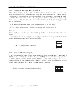
Figure 3.3 illustrates Option 10, which replaces the standard IEC-320 inlet with a 3-pole terminal
strip and provides input surge protection for compliance with ANSI C37.90-1 and IEC 801-4. Input
voltages are: 85 to 250 VAC, 47 to 440 Hz, or 110 to 350 VDC,
<
20 VA typical.
Содержание 1092A
Страница 4: ...iv ...
Страница 18: ...xviii LIST OF TABLES ...
Страница 129: ...C 10 Option 20A Four Fiber Optic Outputs 111 Figure C 7 Option 20A Jumper Locations ...
Страница 131: ...C 11 Option 27 8 Channel High Drive 113 Figure C 8 Option 27 Jumper Locations ...
Страница 148: ...130 Options List Figure C 10 Option 29 Connector Signal Locations ...

