

50
Timing, IRIG-B and Pulses
Option 19
2nd Serial Port
Out-of-Lock
Relay, Option 93
Standard
Outputs*
Standard
RS-232 Port
Antenna
IRIG-B
UNMOD
IRIG-B
MOD
1 PPS
OPTION 7
IEC-320
Power Inlet
Option Panel
03, 20A, 27, 28, 29, 32, 34, 95
LOCK
ERR OK COM
RS-232C
a
Option 19
2nd Serial Port
Out-of-Lock
Relay
Standard
Outputs*
Standard
RS-232 Port
Antenna
IRIG-B
UNMOD
IRIG-B
MOD
1 PPS
LOCK
ERR OK COM
RS-232C
Power Inlet
9 Vdc
500 mA
+
-
ANTENNA
S
E
R
IA
L
N
U
M
B
E
R
B
0
1
2
3
4
OPTION
RS-232
a
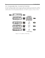
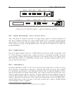
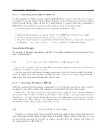
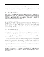
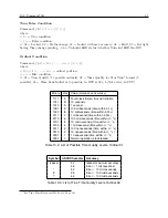
Figure 8.1: Rear Panel Descriptions – optional outputs may be shown
8.2.1
Inputs and Outputs – Port 1, Port 2, Port 3
Three, Phoenix-style, terminal connectors can supply timing signals to external equipment and
may also be configured for input. Two of the outputs (Ports 1 & 3) are designed for digital signals
and one (Port 2) for analog. Signals supplied to the digital drivers include unmodulated IRIG-B,
1 PPS (pulse per second), and programmable pulse. On main boards Option 92 is required for
modulated IRIG-B.
8.2.2
Digital Drivers
Each of the digital outputs is driven by a CMOS 74HCxxx quad driver capable of supplying 75 mA
at 5 VDC, which may be fanned out to a number of devices. To determine the number of devices
you can supply, calculate the load current required by each connected device. For example, if the
IED timing signal input (e.g. IRIG-B003) requires 10 mA, one digital output should be able to
support eight identical devices.
8.2.3
Analog Driver
Modulated IRIG-B is available
at Port 2 of the standard input/output block, and uses an analog
driver exclusively for this purpose. Basically a push-pull audio design, the analog driver supplies
4.5 volts peak-to-peak (Vpp) to a 19.6-ohm source resistor, then to connected equipment. As the
load current increases (by adding external loads), more voltage is dropped across the clock source
resistor causing the drive voltage to decrease. To assure detection by your equipment, make sure
to match the modulated output to within the required voltage range of the receiving equipment.
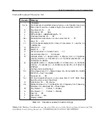
Table 8.1 shows how the actual drive voltage varies with increasing load current. For IED’s with a
restricted input range, it may be necessary to match the available drive voltage to the IED through
a small dropping resistor or amplifier.
1
For main boards choose Option 92; for new main boards it is standard.
Содержание 1092A
Страница 4: ...iv ...
Страница 18: ...xviii LIST OF TABLES ...
Страница 129: ...C 10 Option 20A Four Fiber Optic Outputs 111 Figure C 7 Option 20A Jumper Locations ...
Страница 131: ...C 11 Option 27 8 Channel High Drive 113 Figure C 8 Option 27 Jumper Locations ...
Страница 148: ...130 Options List Figure C 10 Option 29 Connector Signal Locations ...