RAIDER
2000
-
21
-
OPERATOR FOR SWING GATES
English
180
°
180°
90
°
90°
SPACE RESERVED FOR INSTALLER
PLEASE GIVE A COPY OF THIS PAGE TO THE USER
Aprimatic S.p.A.
via Leonardo da Vinci, 414
40059 Villa Fontana di Medicina - Bologna - Italia
Telf. +39 051 6960711 - fax +39 051 6960722
[email protected] - www.aprimatic.com
CHECKING AND ADJUSTMENT
4.
With the wing in movement, check the push force at the
top of the wing with a dynamometer. This must not exceed
15 kg (147 N). If it does, adjust the operating force on the
electronic controller
(see advanced programming in the
Electronic controller Manual
)
.
Warning
!
Once the adjustment has been made, use the dynamometer
again to check that the push force does not exceed the speci
fi
ed
value. If it is still too high, adjust the push force once again.
If the push force needed for the wing movement is still too
high, check the mechanical components for jamming,
check that the gate is vertical (use a plumb line) and check
that the wing moves smoothly. On the basis of the risk
assessment made earlier, install any presence detection
devices necessary (e.g. photocells, sensors).
Information
Compliance with Machinery
Directive 98/37/EC. Once you have installed the equipment,
you must compile a Declaration of Conformity and a Scheduled
Maintenance Plan in compliance with the Machinery
Directive and then hand over copies of these documents
to the user. For maintenance instructions, see par.5.2.
OPERATOR - PERMITTED USES
5.
The automation is designed for use on twin wing gates for
residential use, with a maximum number of 50 opening/
closings per day.
Use with the wing sizes recommended in the technical data
of the product.
Carefully read the general instructions provided.
The operator is non-reversible, so if it is not working or has
no power supply, the gate wing will not be able to move
unless the motor is released
(see
par.5.1
)
.
Motor release for manual gate movement
5.1
(EMERGENCY RELEASE)
In the event of a power or battery failure, you can move the
gate manually by
fi
rst releasing operator.
Warning
!
To release the motor, you must
be on the inside of the gate. If there is no power supply, you
should enter through another entrance.
Releasing the motor
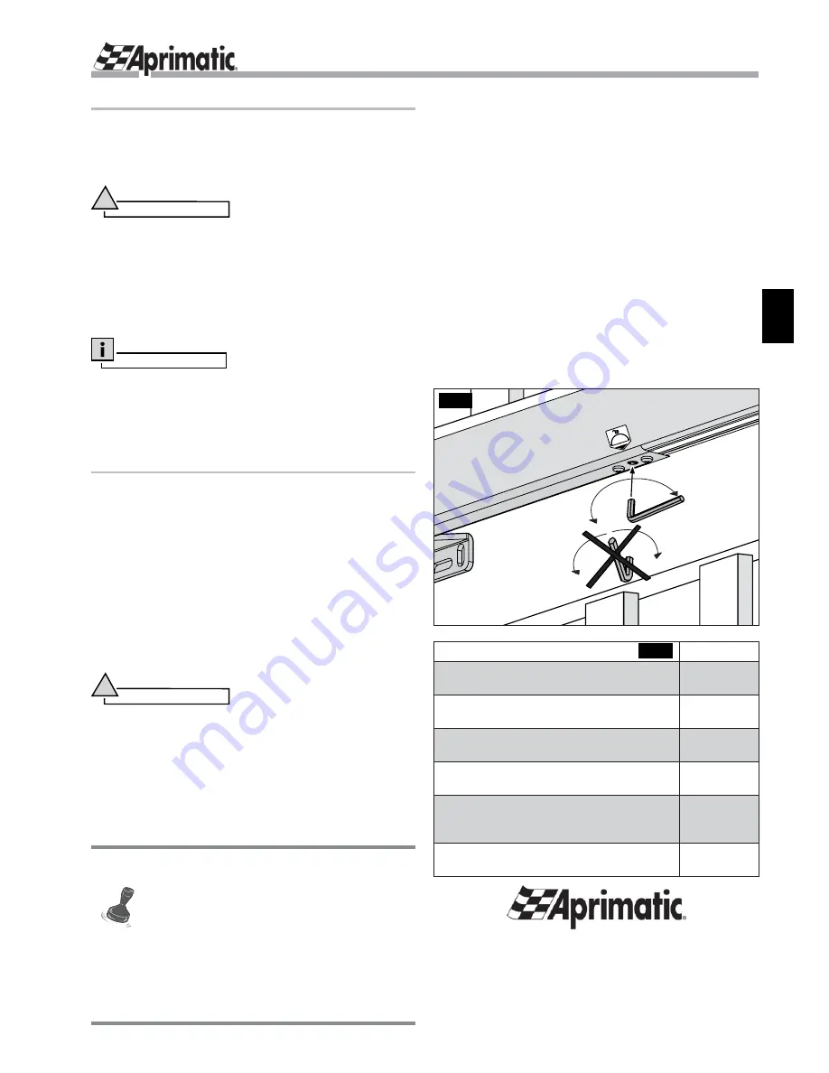
Insert the release Allen key and turn it through 180°
(Fig.18)
(the direction, clockwise or anticlockwise, is unimportant; it is
important that you turn the key through 180°).
Move the gate slowly. Do not push, pull or force it.
Relock the motor
To reslock the motor:
Insert the release Allen key and turn it through 180°
(Fig.18)
(the direction, clockwise or anticlockwise, is unimportant;
it is important that you turn the key through 180°).
Move the gate slowly by hand without forcing it until you hear
the metallic indicating that the mechanical drive has engaged.
Scheduled maintenance
5.2
You should ask the company that installs the automation
provide a scheduled maintenance plan in compliance with
the regulations for this type of equipment. The maintenance
recommended by
Aprimatic S.p.A.
for automation components
is as follows:
Do not throw away old batteries with domestic waste. Dispose of old
batteries using the old battery containers provided at sales outlets.
Batteries are consumables and as such are not covered by
the guarantee.
The maintenance recommended by
Aprimatic S.p.A.
for the
lock parts and the electrical system is listed in
Tab.2
.
Fig.18
operation
frequency
Check the lubrication of the front and rear
mounting pivot of each operator.
Every 6
months
Check that the manual emergency
release is working properly.
Every 6
months
Check that the operator mechanical limit
stops are working ef
fi
ciently (where installed).
Every 6
months
Check the hinges on the gate and ensure
they are properly lubricated.
Every 12
months
Check the strength and stability of the
wing structure. Tighten it where necessary.
Reinforce the structure where necessary.
Every 12
months
Clean the striker plate of the electric lock
(where installed).
Every 6
months
Tab.2


