ADV8003 Hardware Manual
Rev. B, August 2013
360
Table 94: Recommended PSU Decoupling for ADV8003-8 Parts
PSU
Ball Number
Capacitance Required
Placement
AVDD3
G23
4 x 100nF
As close as possible to ADV8003
G23
1 x 10nF
As close as possible to ADV8003
N22
3 x 100nF
As close as possible to ADV8003
N22
1 x 10nF
As close as possible to ADV8003
W22
3 x 100nF
As close as possible to ADV8003
W22
1 x 10nF
As close as possible to ADV8003
n/a
10uF
Place on AVDD3 trace after the EMC filter
PVDD5
M21
2 x 100nF
As close as possible to ADV8003
M21
1 x 10nF
As close as possible to ADV8003
N21
2 x 100nF
As close as possible to ADV8003
N21
1 x 10nF
As close as possible to ADV8003
n/a
10uF
Place on PVDD5 trace after the EMC filter
PVDD6
V21
2 x 100nF
As close as possible to ADV8003
V21
1 x 10nF
As close as possible to ADV8003
W21
2 x 100nF
As close as possible to ADV8003
W21
1 x 10nF
As close as possible to ADV8003
n/a
10uF
Place on PVDD5 trace after the EMC filter
General Digital Inputs and Outputs
The trace length that the digital inputs/outputs have to sink/source should be minimized. Longer traces have higher capacitance, which
requires more current that can cause more internal digital noise. Shorter traces reduce the possibility of reflections. It is recommended to
route traces in the shortest trace length possible and keep the number of layer transitions to a minimum.
If possible, the digital output driver capacitance loading should be limited to less than 15 pF. This can be accomplished easily by keeping
traces short and by connecting the outputs to only one device. Loading the outputs with excessive capacitance increases the current
transients inside the ADV8003, creating more digital noise on its power supplies.
Particular attention must be paid to the routing of clock and sync signals, for example, PCLK, OSD_CLK, HS, OSD_HS, VS, OSD_VS,
DE, OSD_DE, XTALN, and XTALP. Any noise that gets onto these signals can add jitter to the system. Therefore, the trace length should
be minimized, and digital or other high frequency traces should not be run near it.
XTAL and Load Cap Value Selection
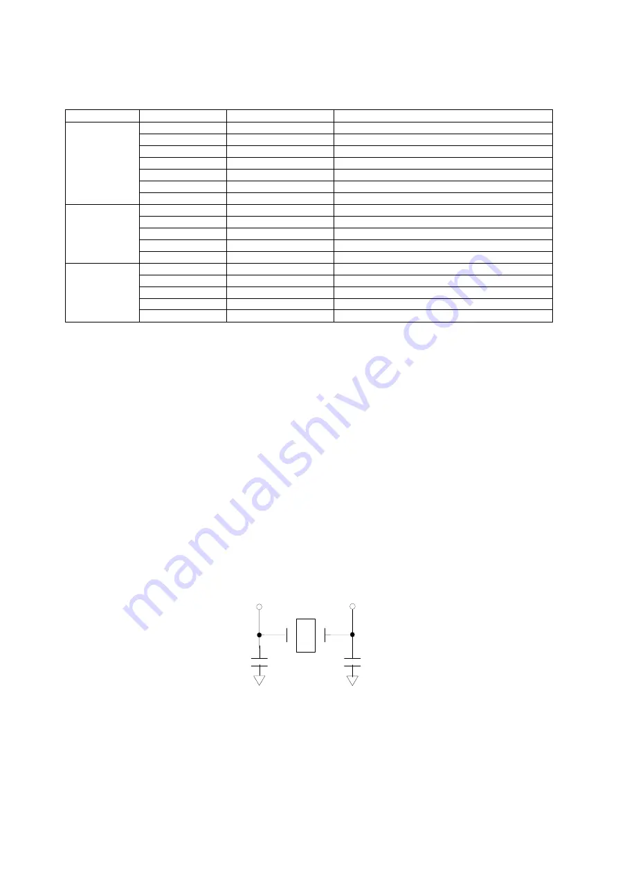
The ADV8003 requires a 27 MHz crystal.
shows an example of a reference clock circuit for the ADV8003. Special care must be
taken when using a crystal circuit to generate the reference clock for the ADV8003. Small variations in reference clock frequency can
impair the performance of the ADV8003.
Figure 138: Crystal Circuit
These guidelines are followed to ensure correct operation:
•
Use the correct frequency crystal (27 MHz recommended). Tolerance should be 50 ppm or better.
•
Know the C
load
for the crystal part number selected. The value of capacitors C1 and C2 must be matched to the C
load
for the
specific crystal part number in the user’s system.
47pF
X
T
A
L
27MHz
C1
C2
47pF
Содержание ADV8003
Страница 364: ...ADV8003 Hardware Manual Rev B August 2013 364 s HPD HEAC CL DA C_GND 5V G_DET Figure 142 ADV8003 Schematic Page 2...
Страница 365: ...ADV8003 Hardware Manual Rev B August 2013 365 Figure 143 ADV8003 Schematic Page 3 Date August 2011 Rev 0...
Страница 366: ...ADV8003 Hardware Manual Rev B August 2013 366 Figure 144 ADV8003 Schematic Page 4...
Страница 367: ...ADV8003 Hardware Manual Rev B August 2013 367 Figure 145 ADV8003 Schematic Page 5...
Страница 368: ...ADV8003 Hardware Manual Rev B August 2013 368 Figure 146 ADV8003 Schematic Page 6...
Страница 369: ...ADV8003 Hardware Manual Rev B August 2013 369 Figure 147 ADV8003 Schematic Page 7...
Страница 370: ...ADV8003 Hardware Manual Rev B August 2013 370 Figure 148 ADV8003 Schematic Page 8 Date August 2011 Rev 0...
Страница 371: ...ADV8003 Hardware Manual Rev B August 2013 371 Figure 149 ADV8003 Schematic Page 9...
Страница 372: ...ADV8003 Hardware Manual Rev B August 2013 372 Figure 150 ADV8003 Schematic Page 10...
Страница 373: ...ADV8003 Hardware Manual Rev B August 2013 373 Figure 151 ADV8003 Schematic Page 11...
Страница 374: ...ADV8003 Hardware Manual Rev B August 2013 374 Figure 152 ADV8003 Schematic Page 12...
Страница 375: ...ADV8003 Hardware Manual Rev B August 2013 375 Figure 153 ADV8003 Schematic Page 13...
Страница 376: ...ADV8003 Hardware Manual Rev B August 2013 376 Figure 154 ADV8003 Schematic Page 14...
Страница 377: ...ADV8003 Hardware Manual Rev B August 2013 377 Figure 155 ADV8003 Schematic Page 15...
Страница 378: ...ADV8003 Hardware Manual Rev B August 2013 378 Figure 156 ADV8003 Schematic Page 16...
Страница 379: ...ADV8003 Hardware Manual Rev B August 2013 379 Figure 157 ADV8003 Schematic Page 17...
Страница 380: ...ADV8003 Hardware Manual Rev B August 2013 380 Figure 158 ADV8003 Schematic Page 18...
Страница 381: ...ADV8003 Hardware Manual Rev B August 2013 381 Figure 159 ADV8003 Schematic Page 19...
Страница 382: ...ADV8003 Hardware Manual Rev B August 2013 382 Figure 160 ADV8003 Schematic Page 20...
Страница 383: ...ADV8003 Hardware Manual Rev B August 2013 383 Figure 161 ADV8003 Schematic Page 21...
Страница 384: ...ADV8003 Hardware Manual Rev B August 2013 384 Figure 162 ADV8003 Schematic Page 22...
Страница 385: ...ADV8003 Hardware Manual Rev B August 2013 385 Figure 163 ADV8003 Schematic Page 23...
Страница 386: ...ADV8003 Hardware Manual Rev B August 2013 386 Figure 164 ADV8003 Schematic Page 24...
Страница 387: ...ADV8003 Hardware Manual Rev B August 2013 387 Figure 165 ADV8003 Schematic Page 25...
Страница 388: ...ADV8003 Hardware Manual Rev B August 2013 388 Figure 166 ADV8003 Schematic Page 26...
Страница 389: ...ADV8003 Hardware Manual Rev B August 2013 389 Figure 167 ADV8003 Schematic Page 27...
Страница 390: ...ADV8003 Hardware Manual Rev B August 2013 390 Figure 168 ADV8003 Schematic Page 28...
Страница 391: ...ADV8003 Hardware Manual Rev B August 2013 391 Figure 169 ADV8003 Schematic Page 29...
Страница 392: ...ADV8003 Hardware Manual Rev B August 2013 392 Figure 170 ADV8003 Schematic Page 30...
Страница 393: ...ADV8003 Hardware Manual Rev B August 2013 393 Figure 171 ADV8003 Schematic Page 31...
Страница 395: ...ADV8003 Hardware Manual Rev B August 2013 395 Figure 173 ADV8003 Layout Page 2...
Страница 396: ...ADV8003 Hardware Manual Rev B August 2013 396 Figure 174 ADV8003 Layout Page 3...
Страница 397: ...ADV8003 Hardware Manual Rev B August 2013 397 Figure 175 ADV8003 Layout Page 4...
Страница 398: ...ADV8003 Hardware Manual Rev B August 2013 398 Figure 176 ADV8003 Layout Page 5...
Страница 399: ...ADV8003 Hardware Manual Rev B August 2013 399 Figure 177 ADV8003 Layout Page 6...
Страница 400: ...ADV8003 Hardware Manual Rev B August 2013 400 Figure 178 ADV8003 Layout Page 7...
Страница 401: ...ADV8003 Hardware Manual Rev B August 2013 401 Figure 179 ADV8003 Layout Page 8...
Страница 402: ...ADV8003 Hardware Manual Rev B August 2013 402 APPENDIX D PACKAGE OUTLINE DRAWING Refer to Section 1 4...
Страница 427: ...ADV8003 Hardware Manual Rev B August 2013 427 P 2 Z Z Z P 1 Z Z Z P 0 Z Z Z...

