ADV8003 Hardware Manual
Rev. B, August 2013
246
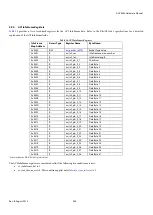
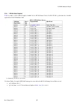
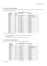
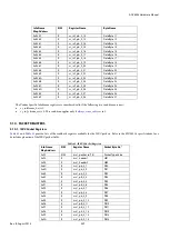
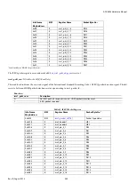
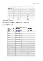
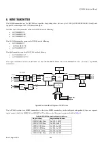
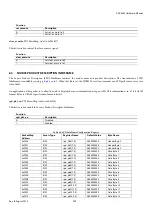
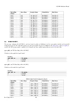
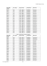
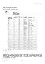
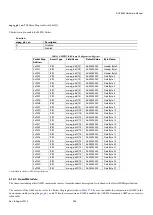
Register Map
Register Map Address
HDMI Tx2 EDID Map
0xF600 – 0xF6FF
HDMI Tx2 CEC Map
0xF800 – 0xF8FF
HDMI Tx2 UDP Map
0xFA00 – 0xFAFF
HDMI Tx2 Test Map
0xFB00 – 0xFBFF
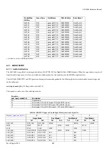
It should be noted that the section on the HDMI transmitter, while referring to HDMI Tx1, also equally applies to HDMI Tx2. The same
register bits and controls as per
6.1.
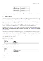
GENERAL CONTROLS
To operate the HDMI Tx core, it is necessary to monitor the Hot Plug Detect (HPD) signal from the downstream sink and power up the
Tx core after the appropriate HPD becomes high. To power up the Tx core,
must be programmed to 0 when the HPD_TX1 pin
is high. The status of the HPD_TX1 pin is provided via
Some registers cannot be written to when the signal on the HPD_TXx input pin is low. When the level on the HPD_TX1 pin goes from
high to low, some registers will be reset to their default value.
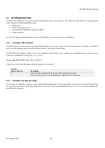
The best method to determine when the level of the signal on the HPD_TXx pin is high is to use the interrupt system. An interrupt can be
enabled to notify level change on the HPD_TXx pin (refer to Section
8 for more details regarding the ADV8003 interrupts).
status bit which can be used to detect the presence of TMDS clock terminations from the
sink. If the ADV8003 detects a voltage level higher than 1.8 V on the clock lines of its TMDS output port,
rx_sense_int
is triggered and
The detection of TMDS clock terminations from downstream sink devices is useful to delay powering up the transmitter sections until the
downstream sink devices are actually ready to receive signals. A typical implementation for a sink is to tie the transmitter 5 V power signal
to HPD through a series resistor. In this case, the ADV8003 will detect a high level on HPD_TX1 (HPD_TX2 for HDMI Tx 2) regardless
of whether or not the downstream sink is powered on and ready to receive a TMDS stream. For this reason, it is best to wait for both the
and
to be high before powering up the Tx core when trying to achieve minimum power consumption.
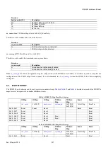
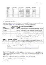
system_pd
, TX2 Main Map,
Address 0xF441[6]
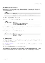
This bit is used to power down the Tx.
Function
system_pd
Description
0
Normal operation
1
Power down Tx
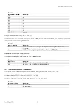
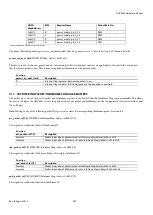
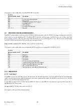
hpd_state
, TX2 Main Map,
Address 0xF442[6] (Read Only)
This bit is used to read back the state of the hot plug detect.
Function
hpd_state
Description
0
Hot Plug Detect inactive (low)
1
Hot Plug active (high)
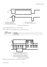
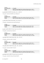
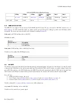
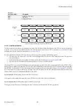
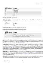
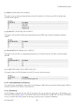
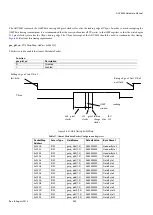
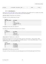
hpd_override[1:0]
, TX2 Main Map,
Address 0xF49F[5:4]
This signal is used to select the source of the internal HPD signal.
Содержание ADV8003
Страница 364: ...ADV8003 Hardware Manual Rev B August 2013 364 s HPD HEAC CL DA C_GND 5V G_DET Figure 142 ADV8003 Schematic Page 2...
Страница 365: ...ADV8003 Hardware Manual Rev B August 2013 365 Figure 143 ADV8003 Schematic Page 3 Date August 2011 Rev 0...
Страница 366: ...ADV8003 Hardware Manual Rev B August 2013 366 Figure 144 ADV8003 Schematic Page 4...
Страница 367: ...ADV8003 Hardware Manual Rev B August 2013 367 Figure 145 ADV8003 Schematic Page 5...
Страница 368: ...ADV8003 Hardware Manual Rev B August 2013 368 Figure 146 ADV8003 Schematic Page 6...
Страница 369: ...ADV8003 Hardware Manual Rev B August 2013 369 Figure 147 ADV8003 Schematic Page 7...
Страница 370: ...ADV8003 Hardware Manual Rev B August 2013 370 Figure 148 ADV8003 Schematic Page 8 Date August 2011 Rev 0...
Страница 371: ...ADV8003 Hardware Manual Rev B August 2013 371 Figure 149 ADV8003 Schematic Page 9...
Страница 372: ...ADV8003 Hardware Manual Rev B August 2013 372 Figure 150 ADV8003 Schematic Page 10...
Страница 373: ...ADV8003 Hardware Manual Rev B August 2013 373 Figure 151 ADV8003 Schematic Page 11...
Страница 374: ...ADV8003 Hardware Manual Rev B August 2013 374 Figure 152 ADV8003 Schematic Page 12...
Страница 375: ...ADV8003 Hardware Manual Rev B August 2013 375 Figure 153 ADV8003 Schematic Page 13...
Страница 376: ...ADV8003 Hardware Manual Rev B August 2013 376 Figure 154 ADV8003 Schematic Page 14...
Страница 377: ...ADV8003 Hardware Manual Rev B August 2013 377 Figure 155 ADV8003 Schematic Page 15...
Страница 378: ...ADV8003 Hardware Manual Rev B August 2013 378 Figure 156 ADV8003 Schematic Page 16...
Страница 379: ...ADV8003 Hardware Manual Rev B August 2013 379 Figure 157 ADV8003 Schematic Page 17...
Страница 380: ...ADV8003 Hardware Manual Rev B August 2013 380 Figure 158 ADV8003 Schematic Page 18...
Страница 381: ...ADV8003 Hardware Manual Rev B August 2013 381 Figure 159 ADV8003 Schematic Page 19...
Страница 382: ...ADV8003 Hardware Manual Rev B August 2013 382 Figure 160 ADV8003 Schematic Page 20...
Страница 383: ...ADV8003 Hardware Manual Rev B August 2013 383 Figure 161 ADV8003 Schematic Page 21...
Страница 384: ...ADV8003 Hardware Manual Rev B August 2013 384 Figure 162 ADV8003 Schematic Page 22...
Страница 385: ...ADV8003 Hardware Manual Rev B August 2013 385 Figure 163 ADV8003 Schematic Page 23...
Страница 386: ...ADV8003 Hardware Manual Rev B August 2013 386 Figure 164 ADV8003 Schematic Page 24...
Страница 387: ...ADV8003 Hardware Manual Rev B August 2013 387 Figure 165 ADV8003 Schematic Page 25...
Страница 388: ...ADV8003 Hardware Manual Rev B August 2013 388 Figure 166 ADV8003 Schematic Page 26...
Страница 389: ...ADV8003 Hardware Manual Rev B August 2013 389 Figure 167 ADV8003 Schematic Page 27...
Страница 390: ...ADV8003 Hardware Manual Rev B August 2013 390 Figure 168 ADV8003 Schematic Page 28...
Страница 391: ...ADV8003 Hardware Manual Rev B August 2013 391 Figure 169 ADV8003 Schematic Page 29...
Страница 392: ...ADV8003 Hardware Manual Rev B August 2013 392 Figure 170 ADV8003 Schematic Page 30...
Страница 393: ...ADV8003 Hardware Manual Rev B August 2013 393 Figure 171 ADV8003 Schematic Page 31...
Страница 395: ...ADV8003 Hardware Manual Rev B August 2013 395 Figure 173 ADV8003 Layout Page 2...
Страница 396: ...ADV8003 Hardware Manual Rev B August 2013 396 Figure 174 ADV8003 Layout Page 3...
Страница 397: ...ADV8003 Hardware Manual Rev B August 2013 397 Figure 175 ADV8003 Layout Page 4...
Страница 398: ...ADV8003 Hardware Manual Rev B August 2013 398 Figure 176 ADV8003 Layout Page 5...
Страница 399: ...ADV8003 Hardware Manual Rev B August 2013 399 Figure 177 ADV8003 Layout Page 6...
Страница 400: ...ADV8003 Hardware Manual Rev B August 2013 400 Figure 178 ADV8003 Layout Page 7...
Страница 401: ...ADV8003 Hardware Manual Rev B August 2013 401 Figure 179 ADV8003 Layout Page 8...
Страница 402: ...ADV8003 Hardware Manual Rev B August 2013 402 APPENDIX D PACKAGE OUTLINE DRAWING Refer to Section 1 4...
Страница 427: ...ADV8003 Hardware Manual Rev B August 2013 427 P 2 Z Z Z P 1 Z Z Z P 0 Z Z Z...

