


Appendix C: Using an IRIS IR Capture Unit
196
VisualArchitect v1.1
CONFIDENTIAL AND PROPRIETARY. COPYRIGHT, AMX LLC, 2006
IRIS - Capturing RC Functions
The two modes you can use to capture RC functions are default and special function (SP Mode).
You use default mode to capture the majority of remote controller (RC) functions.
Before capturing RC functions, make sure the baud rate in the IRIS unit is set properly, and
connected to a PC running VA.
Capturing RC Functions In Default Mode
1.
Make a list of the name and sequence of the remote controller (RC) functions you want to capture.
2.
Connect the IRIS to the PC running VA:
a.
Connect the RS-232 cable to the DB-9 connector on the IRIS unit and the RS-232 port on your
PC.
b.
Set the baud rate in the IRIS unit to match the PC baud rate.
c.
Connect the 12 VDC or 12 VAC power supply to the 12 VDC connector on the IRIS unit.
d.
The ready led lights and "01" appears in the display.
3.
Capture the IR functions of the RC:
a.
Hold the RC approximately 3-inches away from the IR capture window.
b.
Press and hold the first key on the RC to capture the first function.
c.
The signal led will start blinking.
d.
Release the RC key as soon as the ready led goes off.
4.
A set of brackets ([ ]) briefly appears in the display to indicate the RC function is captured. Then,
"01" appears and the Ready and Verify LEDs light.
5.
Hold the RC approximately 3-inches away from the IR capture window. Press and hold the same
key on the RC again to verify the IR function was captured correctly by the IRIS unit.
If the RC function is captured correctly, a pair of brackets ( [ ] ) will briefly flash in the
display. The verify led goes off, "01" appears in the display, and the Send pushbutton's LED
lights.
If an Er message appears in the display, repeat steps 3 and 5. Otherwise, go to step 6.
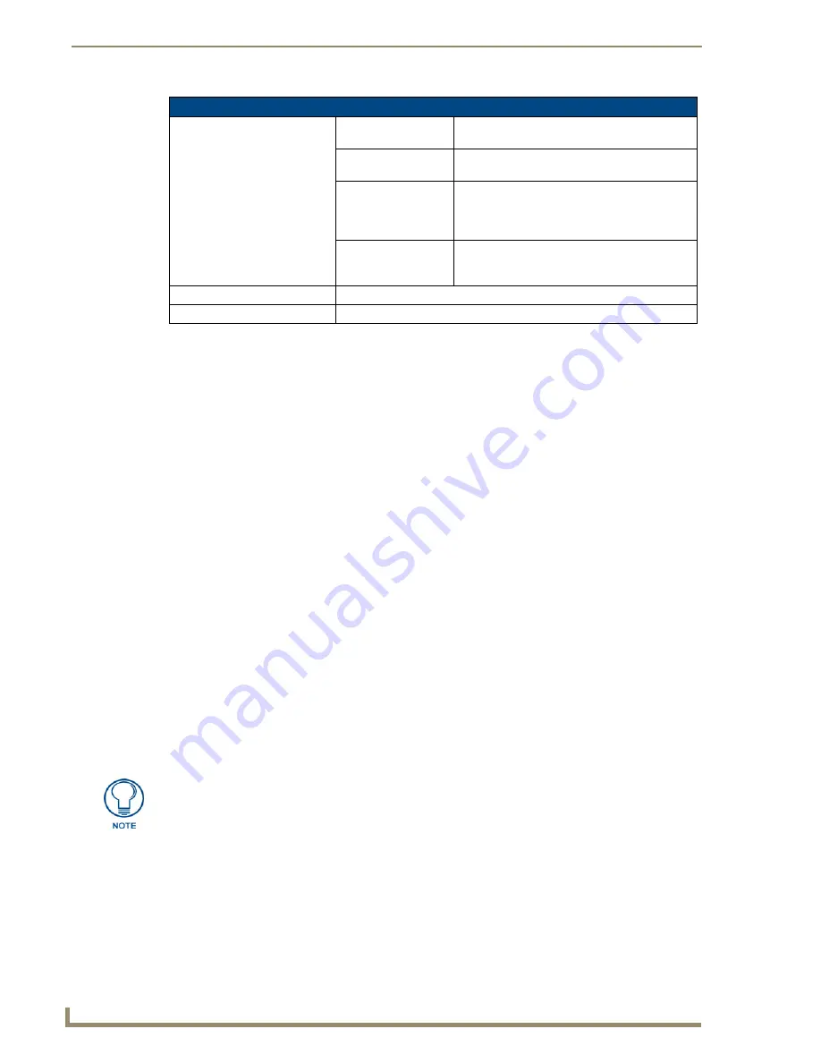
IRIS - Product Specifications (Cont.)
Rear Panel Components:
• 12 VDC/12 VA
Connector:
2-pin (male) 12 VDC or 12 VAC power supply
connector.
• 8-pin data
connector:
Captures wired-IR RC functions. Connect the RC
to the IRE IN or WIRED IN pins.
• RS-232
connectors:
DB-9 connector for data communications with a
PC6-pin RJ-11 modular connector for data com-
munications. Note: The RJ-11 connector is only
used with older SX-DCU+ products.
• Control ports:
IR sensor to receive IR codes; IR serial input for
wired IR codes.DB-9 female connector for Axcess
and PC communication.
Enclosure:
Metal with black matte finish
Includes:
12 VAC power supplyIRLIB software for IBM-compatible computers
The LED will not light if P4 mode is active (refer to the Display Characters and P
Modes topic for details).
Содержание VISUALARCHITECT 1.1
Страница 12: ...x VisualArchitect v1 1 CONFIDENTIAL AND PROPRIETARY COPYRIGHT AMX LLC 2006 Table of Contents ...
Страница 26: ...VisualArchitect v1 1 Overview 14 VisualArchitect v1 1 CONFIDENTIAL AND PROPRIETARY COPYRIGHT AMX LLC 2006 ...
Страница 36: ...Creating a New VA Project 24 VisualArchitect v1 1 CONFIDENTIAL AND PROPRIETARY COPYRIGHT AMX LLC 2006 ...
Страница 102: ...Setting Device Properties 90 VisualArchitect v1 1 CONFIDENTIAL AND PROPRIETARY COPYRIGHT AMX LLC 2006 ...
Страница 106: ...Defining Control Strings 94 VisualArchitect v1 1 CONFIDENTIAL AND PROPRIETARY COPYRIGHT AMX LLC 2006 ...
Страница 158: ...Finishing the Project 146 VisualArchitect v1 1 CONFIDENTIAL AND PROPRIETARY COPYRIGHT AMX LLC 2006 ...
Страница 214: ...Appendix D AMX Icon 2 Character Map 202 VisualArchitect v1 1 CONFIDENTIAL AND PROPRIETARY COPYRIGHT AMX LLC 2006 ...
Страница 240: ...Appendix F The InConcert Resource Center 228 VisualArchitect v1 1 CONFIDENTIAL AND PROPRIETARY COPYRIGHT AMX LLC 2006 ...
Страница 241: ...229 VisualArchitect v1 1 ...


