Installation & Start-Up
|
3-13
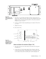
7. Reconnect 1 (L) and 2 (N) wires (Figure 3-7) by screwing in the two
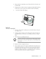
plug screws. Make the ground connection to the threaded chassis stud
(Figure 3-8). Do not use the ground position on the power connector.
Plug in the power connector.
8. Connect a proper, locally recognized plug or terminator to the end of
your cord.
9. Replace rear cover.
10. Reconnect power.
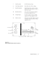
Communication Connections (Figure 3-9)
1. Disconnect the power from the analyzer and remove the rear panel
terminal cover.
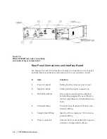
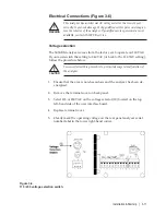
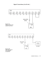
2. Connect the 4 to 20 mA analog output (13) (see Figures 3-10a and
3-10b) and alarm and data valid terminals (14) on the interface board
to the analyzer through the metallic signal conduit (2) (Figure 3-2).
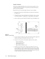
Figure 3-8.
Attach ground wire
to threaded chassis
stud.
Figure 3-9.
Communication
connections on the
3050-RM analyzer
interface board.
Содержание 3050-RM
Страница 11: ... xi ...
Страница 20: ...1 8 3050 RM Moisture Analyzer This page intentionally left blank ...
Страница 24: ...2 4 3050 RM Moisture Analyzer This page intentionally left blank ...
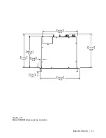
Страница 27: ...Installation Start Up 3 3 Figures 3 1c Model 3050 RM dimensions top and sides ...
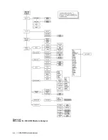
Страница 44: ...4 2 3050 RM Moisture Analyzer Figure 4 2 Menu map for 3050 RM Moisture Analyzer ...
Страница 63: ...Serial Communications 5 7 Figure 5 6 Defined Failure Codes ...
Страница 64: ...5 8 3050 RM Moisture Analyzer Figure 5 7a Variable Table ...
Страница 65: ...Serial Communications 5 9 Figure 5 7b Variable Table ...
Страница 66: ...5 10 3050 RM Moisture Analyzer This page intentionally left blank ...
Страница 78: ...7 2 3050 RM Moisture Analyzer This page intentionally left blank ...
Страница 91: ...Service Parts 8 13 Figure 8 9 Electronic Module ...
Страница 98: ...PPmV Centigrade Fahrenheit lbs mnscf mg Nm3 ppmW ...

