INSTALLATION AND START-UP
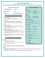
Incoming sample temperature
0 °C and 100 °C
Optimum input gas temperature
60 °C ± 5 °C
Minimum input pressure
20 PSIG
Maximum pressure
50 PSIG
Wiring
22 gauge twisted/shielded pair
Sample Input Tubing
1/8” OD, electropolished 316L VAR SS
Make sure power is off before you begin installation.
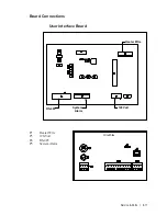
Rear Panel Connections:
1. Remove terminal cover to access interface board.
2. Install main process shut-off valve and pressure regulator at sample tap.
Gas Connections:
1. Remove caps from sample inlet fitting and exhaust fitting and connect
sample input tube and exhaust tube. Vent exhaust to vent system.
2. Select 120 or 240VAC on voltage selector. Mark operating voltage on rear
panel.
Electrical Connections:
1. Make sure the installed power cord has an approved terminator plug per
NEC and CEC regulations.
2. Wire the analyzer per requirements for hazardous or non-hazardous location
per instructions in Chapter 3 of the manual.
Communications Connections:
1. Connect 4-to-20 mA analog output and alarm/data valid terminals on inter-
face board to analyzer using metallic signal conduit.
2. Connect the RS-232 or RS-485 serial communications to analyzer. RS-485
connection shares same cable and metallic signal conduit as analog output
and alarm/data valid contacts.
3.
RS-485 Communications:
RS-485 terminator switch is turned to “ON,”
only
if your unit is a dedicated analyzer or if it is the last analyzer in a chain of
multiple analyzers.
Replace all analyzer covers before continuing.
Initial Startup:
1. Open the main shutoff valve at the source.
2. Turn on the AC power at the source.
3. Once the sample flow starts, the analyzer will be in normal operating mode.
Allow analyzer to warm up for 45 minutes.
Dry Down:
Allow 1 to 3 days for the analyzer to dry down and stabilize. At end of dry down
period, concentration value on display will be stable and recorded data will level
off.
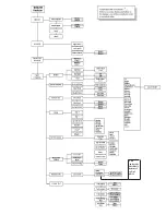
Verify Key:
Hold Outputs
Enable or Disable
Adjust Ofst/Span
Enable or Disable
Verify
Runs internal moisture generator
on demand
Abort
Aborts verify cycle
Alarm Key:
High Limit
Enter value in PPMV
Low Limit
Enter value in PPMV
Enable Alarm
Select enable or disable
Analog Range Key:
Maximum Concentration
Enter moisture concentration equivalent to 20 mA.
Minimum Concentration
Enter moisture concentration equivalent to 4 mA.
Test Config Key:
Display
Contrast
Default is 5
Back Light
Default is ON.
Communication
Baud Rate
Default is 9600
RS-485 Mode
Default is 4-wire
Sample Gas
Select the gas you want to analyze.
Clock
Enter hours using the 24-hour clock.
Verify Schedule
Schedule Type, Day of Week, Day of Month,
Hour and Duration
Production Codes
Production codes for the moisture generator and
reference dryers.
System Test
Test Display
Test Keypad
Test Alarms
Test Analog Output
Test Serial Communications
QUICK REFERENCE CARD
Reference Chapter 3 of the 3050-RM Moisture Analyzer manual.
ANALYZER PARAMETERS
Verify Cycle:
We do not recommend performing a verify cycle during initial startup. The analyzer and its internal generator should be allowed to equilibrate for at
least 24 hours before you run a verify cycle.
Press the
Verify
key and the #8 key (arrow down) until you see “Verify.” Press the
Enter
key to select. The verify cycle takes about 30 minutes.
When the verify cycle is complete, the analyzer adjusts the span and automatically returns to normal sampling.
Содержание 3050-RM
Страница 11: ... xi ...
Страница 20: ...1 8 3050 RM Moisture Analyzer This page intentionally left blank ...
Страница 24: ...2 4 3050 RM Moisture Analyzer This page intentionally left blank ...
Страница 27: ...Installation Start Up 3 3 Figures 3 1c Model 3050 RM dimensions top and sides ...
Страница 44: ...4 2 3050 RM Moisture Analyzer Figure 4 2 Menu map for 3050 RM Moisture Analyzer ...
Страница 63: ...Serial Communications 5 7 Figure 5 6 Defined Failure Codes ...
Страница 64: ...5 8 3050 RM Moisture Analyzer Figure 5 7a Variable Table ...
Страница 65: ...Serial Communications 5 9 Figure 5 7b Variable Table ...
Страница 66: ...5 10 3050 RM Moisture Analyzer This page intentionally left blank ...
Страница 78: ...7 2 3050 RM Moisture Analyzer This page intentionally left blank ...
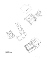
Страница 91: ...Service Parts 8 13 Figure 8 9 Electronic Module ...
Страница 98: ...PPmV Centigrade Fahrenheit lbs mnscf mg Nm3 ppmW ...

