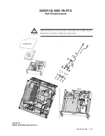
Service & Parts
|
8-15
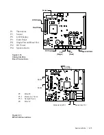
Sensor
LCD Display
Front Panel
DC Power
Fan
(Single)
Fan
(Dual)
System Alarm
Battery
(Solder Side)
RS-232
RS-485
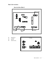
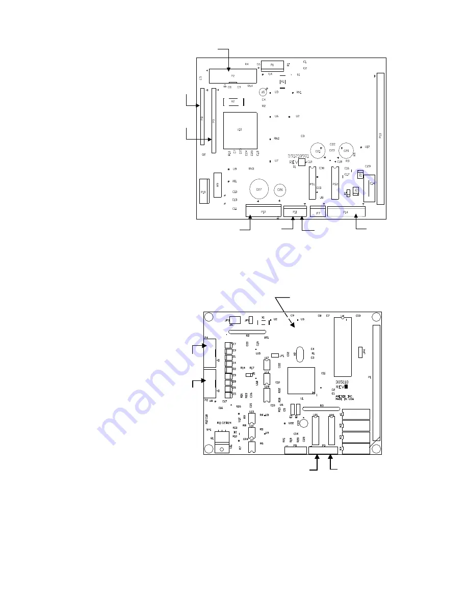
Reference Valve P3-1
Sample Valve P3-3
P1 Thermistor
P2 Sensor
P8
LCD Display
P9
Front Panel
P11 Single Fan and Dual Fan
P12 DC Power
P14 System Alarm
P2 RS-485
P3-1 Reference Valve
P3-3 Sample Valve
P4 RS-232
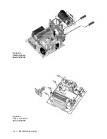
Figure 8-10.
Analog Interface
Board Connections
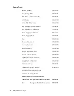
Figure 8-11.
MCU PCB Connections
Содержание 3050-RM
Страница 11: ... xi ...
Страница 20: ...1 8 3050 RM Moisture Analyzer This page intentionally left blank ...
Страница 24: ...2 4 3050 RM Moisture Analyzer This page intentionally left blank ...
Страница 27: ...Installation Start Up 3 3 Figures 3 1c Model 3050 RM dimensions top and sides ...
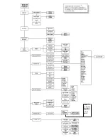
Страница 44: ...4 2 3050 RM Moisture Analyzer Figure 4 2 Menu map for 3050 RM Moisture Analyzer ...
Страница 63: ...Serial Communications 5 7 Figure 5 6 Defined Failure Codes ...
Страница 64: ...5 8 3050 RM Moisture Analyzer Figure 5 7a Variable Table ...
Страница 65: ...Serial Communications 5 9 Figure 5 7b Variable Table ...
Страница 66: ...5 10 3050 RM Moisture Analyzer This page intentionally left blank ...
Страница 78: ...7 2 3050 RM Moisture Analyzer This page intentionally left blank ...
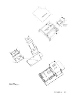
Страница 91: ...Service Parts 8 13 Figure 8 9 Electronic Module ...
Страница 98: ...PPmV Centigrade Fahrenheit lbs mnscf mg Nm3 ppmW ...

