3-6 | 3050-RM Moisture Analyzer
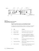
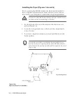
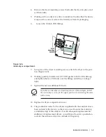
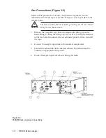
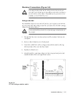
Rear Panel Connections and Interface Board
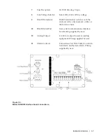
See Figures 3-2 and 3-3 for location of analyzer connections on rear panel
and interface board. Remove terminal cover to access interface board.
# Item
Function
1
Power Conduit
Cable gland for analyzer power cord.
2
Signal Conduit
Cable gland for signal connections.
3
RS-232 Serial Port
User serial communications interface.
Serial wiring supplied by user. Observe
caution regarding use in hazardous loca-
tions.
4
Exhaust Fitting
Vent port for cell exhaust; 1/8-inch com-
pression fitting.
5
Sample Inlet Fitting
Input port for sample gas; 1/8-inch com-
pression fitting.
6
Power connector
Connect hot (1) and neutral (2) to power
connector and ground to chassis.
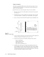
Figure 3-2.
Model 3050-RM rear panel connections
and inside of dryer compartment.
Содержание 3050-RM
Страница 11: ... xi ...
Страница 20: ...1 8 3050 RM Moisture Analyzer This page intentionally left blank ...
Страница 24: ...2 4 3050 RM Moisture Analyzer This page intentionally left blank ...
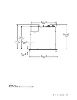
Страница 27: ...Installation Start Up 3 3 Figures 3 1c Model 3050 RM dimensions top and sides ...
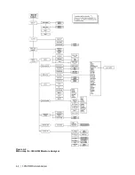
Страница 44: ...4 2 3050 RM Moisture Analyzer Figure 4 2 Menu map for 3050 RM Moisture Analyzer ...
Страница 63: ...Serial Communications 5 7 Figure 5 6 Defined Failure Codes ...
Страница 64: ...5 8 3050 RM Moisture Analyzer Figure 5 7a Variable Table ...
Страница 65: ...Serial Communications 5 9 Figure 5 7b Variable Table ...
Страница 66: ...5 10 3050 RM Moisture Analyzer This page intentionally left blank ...
Страница 78: ...7 2 3050 RM Moisture Analyzer This page intentionally left blank ...
Страница 91: ...Service Parts 8 13 Figure 8 9 Electronic Module ...
Страница 98: ...PPmV Centigrade Fahrenheit lbs mnscf mg Nm3 ppmW ...


