Chapter Two : Hardware Installation
47
Step 5 Attach Internal Cables,
Continued
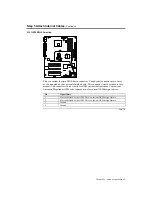
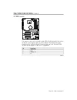
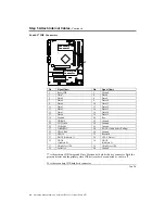
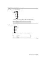
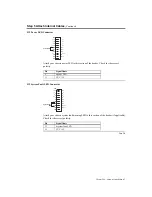
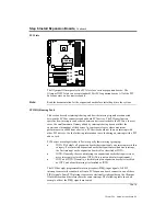
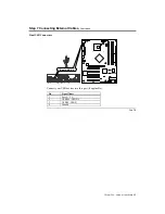
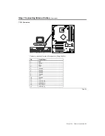
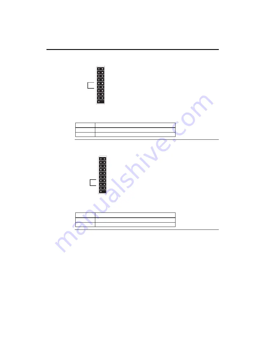
J19 Power LED Connector
1
3
5
7
9
11
13
15
17
19
2
4
6
8
10
12
14
16
18
J19
PWR
GND
IDE
VCC 5V
PWR LED
VCC 3V
SF LED
VCC 5V
NC
NC
RST
GND
NC
GND
INT
GND
NC
SATA LED
VCC 3V
Power LED
Attach your chassis power LED to this section of the header. Check for the correct
polarity.
Pin Signal
Name
9 #power
LED
11
VCC +3 V
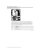
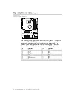
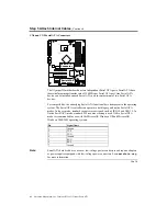
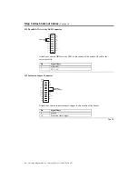
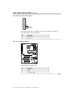
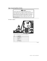
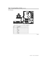
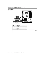
J19 System Fault LED Connector
1
3
5
7
9
11
13
15
17
19
2
4
6
8
10
12
14
16
18
J19
PWR
GND
IDE
VCC 5V
VCC 3V
SF LED
VCC 5V
NC
NC
RST
GND
NC
GND
INT
GND
NC
SATA LED
VCC 3V
System Fault
LED
Attach your chassis system fault/warning LED to this section of the header (if applicable).
Check for the correct polarity.
Pin Signal
Name
13
#system fault LED
15
VCC +5 V
Cont’d
Содержание Olympus III
Страница 1: ...Olympus III User s Guide MAN 875 02 02 04...
Страница 14: ...American Megatrends Inc Olympus III User s Guide Series 875 4 Rear I O Ports...
Страница 20: ...American Megatrends Inc Olympus III User s Guide Series 875 10...
Страница 138: ...American Megatrends Inc Olympus III User s Guide Series 875 128...
Страница 140: ...American Megatrends Inc Olympus III User s Guide Series 875 130...
Страница 146: ...American Megatrends Inc Olympus III User s Guide Series 875 136...

