Chapter Two : Hardware Installation
29
Step 5 Attach Internal Cables,
Continued
CN1 and CN2 ATX Power Supply Connectors, Continued
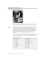
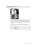
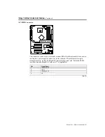
The ATX12V/SSI EPS12V power connector pinout is:
Pin Signal
Name
Pin Signal
Name
1 Ground
5 +12
V
2 Ground
6 +12
V
3 Ground
7 +12
V
4 Ground
8 +12
V
The power supply should match the physical configuration of the chassis. Make sure the
power switch is
Off
before assembly.
Before attaching all components, make sure the proper voltage has been selected. Power
supplies often can run on a wide range of voltages and must be set (usually via a switch)
to the proper range. Use at least a 300-watt ATX power supply, which should have built-
in filters to suppress radiated emissions. Power supply voltage depends upon system load.
For example, +12V rating should be matched to the amount of the external load.
Attach the cables from the power supply to the power connector(s) on the motherboard.
ATX-compatible power supplies can have either one or two 20-pin (or 24-pin)
connectors. You can use either one or both power connectors.
For 24-pin /8-pin SSI EPS12V power supplies, plug the connectors into CN1 and CN2 as
illustrated in the following diagram:
CN1
CN2
Cont’d
Содержание Olympus III
Страница 1: ...Olympus III User s Guide MAN 875 02 02 04...
Страница 14: ...American Megatrends Inc Olympus III User s Guide Series 875 4 Rear I O Ports...
Страница 20: ...American Megatrends Inc Olympus III User s Guide Series 875 10...
Страница 138: ...American Megatrends Inc Olympus III User s Guide Series 875 128...
Страница 140: ...American Megatrends Inc Olympus III User s Guide Series 875 130...
Страница 146: ...American Megatrends Inc Olympus III User s Guide Series 875 136...


