background image

DE-3000+ IOI 8-15 
All rights reserved © ALTRONIC, LLC 2015

58

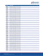
ADDRESS

DESCRIPTION

42971

Channel 22 MIN SENSOR LIMIT (Writable)

42972

Channel 22 MAX SENSOR LIMIT (Writable)

42973

Channel 23 SPAN (Writable)

42974

Channel 23 ZERO (Writable)

42975

Channel 23 MIN SENSOR LIMIT (Writable)

42976

Channel 23 MAX SENSOR LIMIT (Writable)

42977

Channel 24 SPAN (Writable)

42978

Channel 24 ZERO (Writable)

42979

Channel 24 MIN SENSOR LIMIT (Writable)

42980

Channel 24 MAX SENSOR LIMIT (Writable)

42981

Channel 25 SPAN (Writable)

42982

Channel 25 ZERO (Writable)

42983

Channel 25 MIN SENSOR LIMIT (Writable)

42984

Channel 25 MAX SENSOR LIMIT (Writable)

42985

Channel 26 SPAN (Writable)

42986

Channel 26 ZERO (Writable)

42987

Channel 26 MIN SENSOR LIMIT (Writable)

42988

Channel 26 MAX SENSOR LIMIT (Writable)

42989

Channel 27 SPAN (Writable)

42990

Channel 27 ZERO (Writable)

42991

Channel 27 MIN SENSOR LIMIT (Writable)

42992

Channel 27 MAX SENSOR LIMIT (Writable)

42993

Channel 28 SPAN (Writable)

42994

Channel 28 ZERO (Writable)

42995

Channel 28 MIN SENSOR LIMIT (Writable)

42996

Channel 28 MAX SENSOR LIMIT (Writable)

42997

Channel 29 SPAN (Writable)

42998

Channel 29 ZERO (Writable)

42999

Channel 29 MIN SENSOR LIMIT (Writable)

43000

Channel 29 MAX SENSOR LIMIT (Writable)

43001

Channel 30 SPAN (Writable)

43002

Channel 30 ZERO (Writable)

43003

Channel 30 MIN SENSOR LIMIT (Writable)

43004

Channel 30 MAX SENSOR LIMIT (Writable)

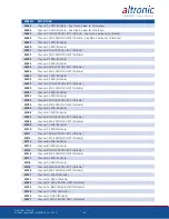
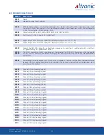
43653

Channel 31 SPAN (Writable – See Note 4 below for Calibration)

43654

Channel 31 ZERO (Writable – See Note 4 below for Calibration)

43655

Channel 31 MIN SENSOR LIMIT (Writable – See Note 4 below for Calibration)

43656

Channel 31 MAX SENSOR LIMIT (Writable – See Note 4 below for Calibration)

43657

Channel 32 SPAN (Writable)

43658

Channel 32 ZERO (Writable)

43659

Channel 32 MIN SENSOR LIMIT (Writable)

43660

Channel 32 MAX SENSOR LIMIT (Writable)

Содержание DE-3000+ Series

Страница 1: ...1 Operating Instructions DE 3000 Series Configurable Safety Shutdown and Control System with Graphing Capabilities Form DE 3000 IOI 8 15 ...

Страница 2: ...options that are enabled using the terminal program 1 3 The DE 3000 has four components 10 color MIDAS HMI G10S0000 computer module DE 3000 terminal module 691171 1 and power supply module 691122 1 The MIDAS HMI and the computer module communicate via the Ethernet port using a CAT 5e cable The computer module connects to the terminal module via a DB 25 cable An additional terminal board may be add...

Страница 3: ...lish communication with the MIDAS HMI 3 0 COMPUTER MODULE DE 3000 3 1 The Computer Module is designed to be rail mounted and is the interface be tween the Terminal and 10 MIDAS HMI and to other systems It typically plugs directly into the Terminal Module using the DB 25 connectors and is held to gether with screws and screw locks 3 2 The computer module must be supplied with 10 32VDC 2A Max curren...

Страница 4: ...e IP configuration of the system to match their network To change the IP configuration type in the new IP settings under Change Settings to and press Apply The web page will reload Reboot the computer module and access the web browser again The new IP set tings should have been accepted by the computer module 3 5 The Serial Port Settings page displays the serial port configuration of the DE 3000 T...

Страница 5: ...re used as follows OUT 1 slot must be used to trip the fuel valve and OUT 2 slot must be used to short the ignition If 12 24Vdc is lost to the DE 3000 annunciator system the custom Output Modules will trip the fuel valve and short the igni tion shutdown lead This mimics the fail safe operation of a normally closed Output Module and therefore the LED will be ON in the normal run condition and OFF f...

Страница 6: ... three wires connect directly to the back of the Terminal Module using cable assembly P N 693008 x 5 5 DIFFERENTIAL MEASUREMENTS Differential pressures or temperatures may be measured by using two consecu tive channels The transducers used to measure differential values must be of the exact same type and range The first channel of the pair will display the basic parameter it is monitoring and the ...

Страница 7: ... a DB 25 male female cable such as P N 693115 1 is used to elec trically connect these modules The operating temperature range of the Power Supply Module is 31 F to 176 F 35 C to 80 C 6 3 TERMINAL MODULE Mount the Terminal Module either on the bottom or the side of the main panel The Terminal Module and Power Supply Module can be rail mounted onto com mercially available 32 or 35mm DIN mounting ra...

Страница 8: ...ld be connected to earth ground protective earth The chassis ground is not connected to signal common of the unit Maintaining isolation between earth ground and signal common is not required to operate the unit But other equipment connected to this unit may require isolation be tween signal common and earth ground To maintain isolation between signal common and earth ground care must be taken when...

Страница 9: ...ired the same as the sensor switches and can be used with either normally open or normally closed contacts Use a wire size between 16 AWG max and 24 AWG min to connect the sen sor switches to the terminal strip connector Strip the insulation back 3 8 twist the exposed wires tightly together Insert the exposed wire completely into the terminal strip and securely tighten the clamping screw Wires run...

Страница 10: ... and take precautions against later damage from vibration abrasion or liquids in conduits In addition it is essential that the following practices be adhered to A Never run sensor wires in the same conduit with ignition wiring or other high energy wiring such as AC line power B Keep secondary wires to spark plugs and other high voltage wiring at least eight inches 200mm away from sensor and sensor...

Страница 11: ...nects to one magnetic pickup input the other pickup wire connects to the minus terminal on the Power Supply Module The T terminal connects to one magnetic pickup input the other pickup wire connects to the terminal on the terminal module THE MAGNETIC PICKUP INPUT MUST BE USED FOR APPLICATIONS ENABLING THE OPTIONAL AUTO START OR OEM ENGINE CONTROL FUNCTION 8 0 HAZARDOUS AREA OPERATION 8 1 The DE 30...

Страница 12: ...d through the Main Menu and MIDAS HMI Utility screens as shown below The HMI Utility screen can be accessed by clicking on the HMI UTILITY button on the Main Menu screen To return from the HMI Utility screen to Main Menu screen click on the MAIN MENU button on the HMI Utility screen NOTE THE SCREENS SHOWN IN THIS SECTION ON THE HMI REFLECT A GENERAL LAYOUT AND MAY APPEAR DIFFERENTLY DUE TO DIFFERE...

Страница 13: ...tton on the Main Menu screen When the Log in popup appears the status displays whether the user is logged in or not If the LOGOUT is selected click on the LOGIN button and enter the credentials Once the credentials are authorized the LOGIN button will be selected show ing that the user has successfully been logged in ...

Страница 14: ...entials would be required before accessing the write control popup Once the popup appears press the WRITE button to en able write control The write control should be set to Read mode when not editing DE 3000 controller registers To avoid the write control from staying at Write all the time a timer is implemented on the MIDAS HMI that changed the write control to Read mode after it expires The defa...

Страница 15: ...R button on the HMI Utility After the credentials are verified the write control timer popup appears The Control Write Time in sec can be modified to increase or decrease the time for the write feature to expire The Time Elapsed in sec shows how much time is left before the write control will revert to Read mode ...

Страница 16: ...place that needs to be setup before alarms will become active The first step is to enable the alarm on the DE 3000 system By default the DE 3000 system have the alarms disabled To enable press the ENABLE ALARMS button on the HMI Utility page After the credentials are verified the Alarm Enable Disable popup screen appears Click on the ENABLE button to enable the alarms on the DE 3000 system ...

Страница 17: ...ge When the High Low Alarms are armed and the alarm condition is met the alarms show up as yellow on the data box and the alarm strip describing the nature of the alarm appears at the bottom of the screen 9 6 In addition to the Main Menu and HMI Utility screens all the screens on the MIDAS HMI can be accessed through the Menu Popup at the bottom of every HMI screen ...

Страница 18: ...LTRONIC LLC 2015 18 Once the Menu popup is pressed screen navigation buttons appear at the bot tom of the screen To view more navigation buttons press the EXTENDED MENU button The Menu Popups can be canceled by pressing the red exit button ...

Страница 19: ... previous category of screens while the maroon arrow keys are used to move to the next or previous screen 9 8 The Home Screen can be accessed by clicking on the HOME button on the Main Menu screen Through the Home screen the user can control the opera tion and monitor the status of the DE 3000 controller The screenshot shows the Home screen for a DE 3000 system Home screens may vary based on the p...

Страница 20: ...C 2015 20 9 9 The START button on the Home screen sends a command to the DE 3000 controller to start 9 10 STOP key is used for a manual stop condition By pressing the STOP key the controller activates the configured output modules in the power supply ...

Страница 21: ...popup explaining why the menu is unable to ex ecute In the screenshot below the reason Lube Flow is inactive is because none of the channels on the DE 3000 are configured as lube monitoring sensors 9 12 TEST key disables the output modules and allows the user to fault or test the input sensors Every time the test button is pressed the test timer resets to its preset value ...

Страница 22: ...ll rights reserved ALTRONIC LLC 2015 22 9 13 CANCEL TIMERS key cancels all timers including the cool down timer 9 14 RESET key clears all past faulted points and resets all input and output timers to their preset values ...

Страница 23: ...erved ALTRONIC LLC 2015 23 9 15 When the DE 3000 controller is running the COOLDOWN button can be pressed to initiate the cool down timer Once the cool down timer is initiated it can be cancelled by pressing the CAN CEL TIMERS button ...

Страница 24: ...DOWN status 9 16 To access the Linear Ramp popup click on the LINEAR RAMP button on the Home screen After authorizing login credentials the MIDAS HMI displays the Linear Ramp popup where Var Low and High values along with the correspond ing output limits can be set up by the user Make sure the write command is enabled before writing any new value to the controller ...

Страница 25: ...lse value can be modified if the write command and the security credentials are enabled 9 18 The Terminal Module screens can be accessed by clicking on the TERMINAL MOD button on the Main Menu screen Through the Terminal Module screen the user can monitor up to 20 channels in one screen Navigation to all the channels is made easy through the labeled buttons navigating to all the screens in the IO ...

Страница 26: ...annels in one screen Navigation to all the channels is made easy through the labeled buttons navigat ing to all the screens in the IO Status category The screenshot above shows the Channel Status screen for channels 1 10 This screen can only be used to monitor as the user is not logged in When the user logs in with the correct credentials the header of the screen changes to Alarm SPs and the Alarm...

Страница 27: ...er the high or low parameters are armed and whether there is an alarm or shutdown condi tion present on each channel 9 20 The Process screen can be accessed by pressing the PROCESS button on the Main Menu screen Through the Process screen the user can monitor and modify if logged in channel setpoints related to the process ...

Страница 28: ...or the chan nels related to the engine motor 9 22 The PID screens can be accessed by pressing the PID 1 2 and PID 3 4 if using a second terminal board buttons on the Main Menu screen Through the PID screen the user can monitor the PID values in bar graph form for better visualization If logged in the user can also modify PID setpoint and PID param eters P I D make sure write control is enabled ...

Страница 29: ...he operator can also modify the 4 20mA output Before modifying the 4 20mA output make sure that the rate of change ROC is setup to an appropriate value The Rate of change is the increment decrement amount per key press of the 4 20mA in manual mode The TREND button can be pressed to display the PID parameter in a trend The dynamic scaling allows the user to zoom in or out as needed ...

Страница 30: ...s for up to 10 channels at the same time Navigation to all the channels is made easy through the labeled buttons navigating to all the screens in the IO Status category The user can modify the setpoints on the Control SP screen when logged in When the credentials are verified and the Control SP screen selected the header of the screen changes to Control Setpoints and if the control write is enable...

Страница 31: ...ting down the input is not armed Navigation to all channels is simplified via the labeled buttons navigating to all the screens in the IO Status category 9 25 The Raw Modbus Register screens can be accessed by pressing the RAW VALUES button on the Main Menu screen Through the Raw Modbus Regis ter screen the user can monitor the actual values that are residing inside the DE 3000 controller at any t...

Страница 32: ...the log values are also saved on the SD card installed on the MIDAS HMI 9 27 The SD Card Status popup can be accessed by pressing the SD CARD STA TUS button on the MIDAS HMI Utility screen The SD Card Status popup gives detail on the SD card capacity and the status while giving the user the ability to format or eject the card The GENERATE SP REPORTS button allows the user to save current setpoint ...

Страница 33: ...IDAS HMI Utility screen The CPU Termi nal Board Firmware popup displays the date of the firmware currently installed on the DE 3000 computer module and the terminal board 9 29 The System Status popup can be accessed by pressing the SYSTEM STATUS button on the MIDAS HMI Utility screen The System Status popup displays the MIDAS HMI battery and communication status ...

Страница 34: ...DE 3000 computer module The user can setup a new IP configuration by inputting the IP Address Subnet Mask and Gateway on the data entry boxes and then clicking the Set IP to Ethernet Port 1 button The MIDAS HMI re boots before saving the new IP configuration into the system 9 31 The Time Manager Popup can be accessed by pressing the TIME MANAGER button on the MIDAS HMI Utility screen The Time Mana...

Страница 35: ...he events that have occurred on the DE 3000 controller This information is also saved on the SD card 9 33 The Alarm Viewer can be accessed by pressing the red triangle button on the bezel of the MIDAS HMI The Alarm viewer displays the Active and Unaccepted alarms on the DE 3000 controller If an alarm is no longer active the user can press the Acknowledge Alarms button to accept the alarm ...

Страница 36: ...ING Timer 2 timers to a count of zero This is system STATE 1 The PRE LUBE and DELAY BEFORE CRANKING timers will both begin counting at this time but they each have an independently set value so that the PRE LUBE pump can be set to run prior to the cranking only or thru the cranking cycle or until some point in time after the engine starts If an optional pressure setpoint is going to be used to ter...

Страница 37: ...s 1 and 2 of the power supply module and the engine should begin running 11 8 STATE 6 ENGINE STARTED As the engine speed increases the user programmable CRANK DISCONNECT speed switch function will automatically disable the starter at the selected RPM by de energizing OUTPUT 3 This is the beginning of system STATE 6 on the sequence chart If the crank disconnect RPM is not reached within a user pro ...

Страница 38: ...le on the power supply board output are shown below Auto Start Signal OR Stop Fault ON Time during run ON Time 1 5 s 12 2 The OEM ENGINE CONTROL sequence must begin from an engine stopped condition When a DE has been configured for OEM ENGINE CONTROL and an auto start is signaled by grounding the R terminal on the terminal board or a command from the HMI Lube turns ON the Crank Multi Start disconn...

Страница 39: ...3 15psi is used then the 4 20mA output is connected to an appropriate I P transducer 13 4 The CAPACITY control output of the DE 3000 is available in two formats to drive the most common actuating systems The first output format is an indus try standard 4 20mA current loop used for continuously adjustable sometimes referred to as linear control The 4 20mA output would typically be used to interface...

Страница 40: ...tor driven compressors a motor current sensor or kW sensor works in the same manner as the engine manifold pressure sensor on a gas engine 13 6 When programming the DE 3000 system the basic relationship of the Primary Control Inputs CH1 CH2 S01 Primary Control Outputs AO1 and AO2 and Output Actuators needs to be defined The relationship between a Primary Control Input and Primary Control Output is...

Страница 41: ...e PC terminal program to initially configure the system 15 0 CASCADE CONTROL Channel 01 is used to drive the output on A02 CASCADE RPM control enables engine speed to be controlled based on the control setpoint on Loop 1 Once Loop 1 is forcing a maximum output Loop 2 will drive an output to increase engine speed up to a maximum RPM in order to achieve the control setpoint on Channel 01 See section...

Страница 42: ...to the STATUS RUNNING home screen and does not reset the class B C and output timers Pressing the RESET key takes the user to the STATUS TIMERS ACTIVE home screen with the class B C and output timers reset 19 0 COOL DOWN 19 1 The cool down mode enables the engine to enter a state before shutting down where a number of sensors may normally fault low Class B and C channels that are configured for co...

Страница 43: ... ENGINE START STOP FAULT ON OFF INTEGRATED OUTPUT TIMER INTEGRATED TIMER OUTPUT DELAY 22 0 PROGRAMMING THE DE 3000 22 1 The DE 3000 must first be programmed prior to use on an engine Use the DE 3000 PC terminal program to complete this task It can be downloaded from the Altronic website at http www altronic llc com catalog downloads shtml under the Terminal Programs section 23 0 MODBUS FUNCTIONALI...

Страница 44: ...ys the next character This may be used for MMI MIDAS applications 40080 Writable register for the keypad input Use function 6 to perform the write See Key Press Table for the values for each key This register along with 40030 40069 may be used in conjunction with a MMI Red Lion to press keys on the keypad 40090 Channel 1 input reading signed 40091 Channel 2 input reading signed 40092 Channel 3 inp...

Страница 45: ... reading signed 40130 Channel 41 input reading signed 40131 Channel 42 input reading signed 40132 Channel 43 input reading signed 40133 Channel 44 input reading signed 40134 Channel 45 input reading signed 40135 Channel 46 input reading signed 40136 Channel 47 input reading signed 40137 Channel 48 input reading signed 40138 Channel 49 input reading signed 40139 Channel 50 input reading signed 4014...

Страница 46: ...0216 Firmware month of 1st terminal 1 12 40217 Firmware day of 1st terminal 1 31 40218 Firmware year of 1st terminal 00 99 40219 Firmware month of 2nd terminal 1 12 0 DNE 40220 Firmware day of 2nd terminal 1 31 0 DNE 40221 Firmware year of 2nd terminal 00 99 40222 Time left until a MultiStart Restart attempt seconds 0 if not counting down 40223 Ch 01 16 bitmap of armed 1 not armed 0 status 40224 C...

Страница 47: ...e 41037 Channel 4 low safety setpoint Writable 41038 Channel 4 high safety setpoint Writable 41039 Channel 4 low control setpoint Writable 41040 Channel 4 high control setpoint Writable 41041 Channel 5 low safety setpoint Writable 41042 Channel 5 high safety setpoint Writable 41043 Channel 5 low control setpoint Writable 41044 Channel 5 high control setpoint Writable 41045 Channel 6 low safety set...

Страница 48: ...rol setpoint Writable 41080 Channel 14 high control setpoint Writable 41081 Channel 15 low safety setpoint Writable 41082 Channel 15 high safety setpoint Writable 41083 Channel 15 low control setpoint Writable 41084 Channel 15 high control setpoint Writable 41085 Channel 16 low safety setpoint Writable 41086 Channel 16 high safety setpoint Writable 41087 Channel 16 low control setpoint Writable 41...

Страница 49: ...ety setpoint Writable 41123 Channel 25 low control setpoint Writable 41124 Channel 25 high control setpoint Writable 41125 Channel 26 low safety setpoint Writable 41126 Channel 26 high safety setpoint Writable 41127 Channel 26 low control setpoint Writable 41128 Channel 26 high control setpoint Writable 41129 Channel 27 low safety setpoint Writable 41130 Channel 27 high safety setpoint Writable 41...

Страница 50: ...afety setpoint Writable 41166 Channel 35 high safety setpoint Writable 41167 Channel 35 low control setpoint Writable 41168 Channel 35 high control setpoint Writable 41169 Channel 36 low safety setpoint Writable 41170 Channel 36 high safety setpoint Writable 41171 Channel 36 low control setpoint Writable 41172 Channel 36 high control setpoint Writable 41173 Channel 37 low safety setpoint Writable ...

Страница 51: ...trol setpoint Writable 41209 Channel 46 low safety setpoint Writable 41210 Channel 46 high safety setpoint Writable 41211 Channel 46 low control setpoint Writable 41212 Channel 46 high control setpoint Writable 41213 Channel 47 low safety setpoint Writable 41214 Channel 47 high safety setpoint Writable 41215 Channel 47 low control setpoint Writable 41216 Channel 47 high control setpoint Writable 4...

Страница 52: ...hannel 56 low control setpoint Writable 41252 Channel 56 high control setpoint Writable 41253 Channel 57 low safety setpoint Writable 41254 Channel 57 high safety setpoint Writable 41255 Channel 57 low control setpoint Writable 41256 Channel 57 high control setpoint Writable 41257 Channel 58 low safety setpoint Writable 41258 Channel 58 high safety setpoint Writable 41259 Channel 58 low control se...

Страница 53: ... and time 43189 Channel 9 low setpoint class and time 43190 Channel 9 high setpoint class and time 43191 Channel 10 low setpoint class and time 43192 Channel 10 high setpoint class and time 43193 Channel 11 low setpoint class and time 43194 Channel 11 high setpoint class and time 43195 Channel 12 low setpoint class and time 43196 Channel 12 high setpoint class and time 43197 Channel 13 low setpoin...

Страница 54: ...Channel 30 low setpoint class and time 43232 Channel 30 high setpoint class and time 43233 Channel S01 low setpoint class and time 43234 Channel S01 high setpoint class and time 43941 Channel 31 low setpoint class and time See Note 3 below 43942 Channel 31 high setpoint class and time 43943 Channel 32 low setpoint class and time 43944 Channel 32 high setpoint class and time 43945 Channel 33 low se...

Страница 55: ...me 43979 Channel 50 low setpoint class and time 43980 Channel 50 high setpoint class and time 43981 Channel 51 low setpoint class and time 43982 Channel 51 high setpoint class and time 43983 Channel 52 low setpoint class and time 43984 Channel 52 high setpoint class and time 43985 Channel 53 low setpoint class and time 43986 Channel 53 high setpoint class and time 43987 Channel 54 low setpoint cla...

Страница 56: ...ritable 42901 Channel 5 SPAN Writable 42902 Channel 5 ZERO Writable 42903 Channel 5 MIN SENSOR LIMIT Writable 42904 Channel 5 MAX SENSOR LIMIT Writable 42905 Channel 6 SPAN Writable 42906 Channel 6 ZERO Writable 42907 Channel 6 MIN SENSOR LIMIT Writable 42908 Channel 6 MAX SENSOR LIMIT Writable 42909 Channel 7 SPAN Writable 42910 Channel 7 ZERO Writable 42911 Channel 7 MIN SENSOR LIMIT Writable 42...

Страница 57: ...SPAN Writable 42946 Channel 16 ZERO Writable 42947 Channel 16 MIN SENSOR LIMIT Writable 42948 Channel 16 MAX SENSOR LIMIT Writable 42949 Channel 17 SPAN Writable 42950 Channel 17 ZERO Writable 42951 Channel 17 MIN SENSOR LIMIT Writable 42952 Channel 17 MAX SENSOR LIMIT Writable 42953 Channel 18 SPAN Writable 42954 Channel 18 ZERO Writable 42955 Channel 18 MIN SENSOR LIMIT Writable 42956 Channel 18...

Страница 58: ...42990 Channel 27 ZERO Writable 42991 Channel 27 MIN SENSOR LIMIT Writable 42992 Channel 27 MAX SENSOR LIMIT Writable 42993 Channel 28 SPAN Writable 42994 Channel 28 ZERO Writable 42995 Channel 28 MIN SENSOR LIMIT Writable 42996 Channel 28 MAX SENSOR LIMIT Writable 42997 Channel 29 SPAN Writable 42998 Channel 29 ZERO Writable 42999 Channel 29 MIN SENSOR LIMIT Writable 43000 Channel 29 MAX SENSOR LI...

Страница 59: ...e 43679 Channel 37 MIN SENSOR LIMIT Writable 43680 Channel 37 MAX SENSOR LIMIT Writable 43681 Channel 38 SPAN Writable 43682 Channel 38 ZERO Writable 43683 Channel 38 MIN SENSOR LIMIT Writable 43684 Channel 38 MAX SENSOR LIMIT Writable 43685 Channel 39 SPAN Writable 43686 Channel 39 ZERO Writable 43687 Channel 39 MIN SENSOR LIMIT Writable 43688 Channel 39 MAX SENSOR LIMIT Writable 43689 Channel 40...

Страница 60: ...SPAN Writable 43722 Channel 48 ZERO Writable 43723 Channel 48 MIN SENSOR LIMIT Writable 43724 Channel 48 MAX SENSOR LIMIT Writable 43725 Channel 49 SPAN Writable 43726 Channel 49 ZERO Writable 43727 Channel 49 MIN SENSOR LIMIT Writable 43728 Channel 49 MAX SENSOR LIMIT Writable 43729 Channel 50 SPAN Writable 43730 Channel 50 ZERO Writable 43731 Channel 50 MIN SENSOR LIMIT Writable 43732 Channel 50...

Страница 61: ...annel 59 MIN SENSOR LIMIT Writable 43768 Channel 59 MAX SENSOR LIMIT Writable 43769 Channel 60 SPAN Writable 43770 Channel 60 ZERO Writable 43771 Channel 60 MIN SENSOR LIMIT Writable 43772 Channel 60 MAX SENSOR LIMIT Writable 44609 Hourmeter run time high word See Note 5 below 44610 Hourmeter run time low word See Note 5 below 44611 Service meter 1 hours remaining high word See Note 6 below 44612 ...

Страница 62: ...high word 44640 Service meter 4 reset value hours low word 44641 Service meter 5 reset value hours high word 44642 Service meter 5 reset value hours low word 44643 Service meter 6 reset value hours high word 44644 Service meter 6 reset value hours low word 44645 Service meter 7 reset value hours high word 44646 Service meter 7 reset value hours low word 44647 Service meter 8 reset value hours high...

Страница 63: ...Write Counter will increment when 1 A Modbus function code 6 preset single register occurs 2 A value is modified through the keypad Applicable to DE 3000 Enhanced only Register 40228 ASCII Write Counter will increment when 1 A XXXP command occurs writing to the display board 2 A 0XT command occurs writing to a terminal board These registers cannot be written to and cycling power to the unit will n...

Страница 64: ...5 01000000 00111100 43176 10000000 00001010 26 4 Note 4 Calibration 1 The ZERO and SPAN Modbus registers are used to tweak the sensors typically pressure to read a known value SPAN Slope of the line relating the sensor range to the domain Typical val ues would be from 1 255 It is recommended that this value be read and then changed by one This value should not be greater than 512 ZERO Y intercept ...

Страница 65: ... 47947 18 19 47948 ASCII char 20 Each meter uses the same format as above starting with the low byte on the first register and ending on the high byte of the eleventh register The starting and ending index for each meter label is Description Starting Register Ending Register Hourmeter 47938 47948 Service Meter 1 47954 47964 Service Meter 2 47970 47980 Service Meter 3 47986 47996 Service Meter 4 48...

Страница 66: ...ent Con trol setpoints may also be used to implement corrective actions to prevent overstress of components or to notify personnel of potential problems before they become se vere enough to cause a shutdown CRANK DISCONNECT The RPM setting at which output 3 of the power supply will be de energized This will de energize the starting device CRANKING DELAY The time after the auto start command before...

Страница 67: ...he proportional band is used to tune the response of the controller to the characteristic behavior of the equip ment being controlled Proportional band is the inverse of gain expressed as a percentage A proportional band setting of 10 is equal to a gain setting 10 a propor tional band setting of 20 is equal to a gain of 5 etc The smaller the proportional band setting the greater the controller res...

Страница 68: ...DAS HMI MAIN MENU 12 10 0 MANUAL MODE 36 11 0 AUTO START 36 12 0 OEM ENGINE CONTROL 38 13 0 SELECTING A CONTROL STRATEGY 39 14 0 PID CONTROL 41 15 0 CASCADE CONTROL 41 16 0 LINEAR RAMP CONTROL 41 17 0 PULSE CONTROL 41 18 0 TEST MODE 42 19 0 COOL DOWN 42 20 0 CALIBRATION OF TRANSDUCER 42 21 0 INTEGRATED TIMER OUTPUTS 43 22 0 PROGRAMMING THE DE 3000 43 23 0 MODBUS FUNCTIONALITY 43 24 0 MODBUS REGIST...

Страница 69: ...OPERATION FIG 2 DE 3000 SYSTEM DIAGRAM FIG 3 DE 3000 TERMINAL MODULE AND POWER SUPPLY MODULE FIG 4 WIRING DIAGRAM GENERAL HOOK UP FIG 5 WIRING DIAGRAM PERSONAL COMPUTER FIG 6 WIRING DIAGRAM SENSOR AND TRANSDUCER INPUTS FIG 7 WIRING DIAGRAM CURRENT LOOP OUTPUTS FIG 8 WIRING DIAGRAM DIGITAL OUTPUT SWITCHES ...

Страница 70: ...SECONDS THEN OFF ON FOR TIMER T2 SECONDS THEN OFF ON FOR TIMER T2 SECONDS THEN OFF ON FOR TIMER T2 SECONDS THEN OFF ON FOR TIMER T2 SECONDS THEN OFF ON FOR TIMER T2 SECONDS OR USER OFF RPM OFF OFF ANALOG OUT AO1 VALUE USER DEFAULT VALUE USER DEFAULT VALUE USER DEFAULT VALUE USER DEFAULT VALUE USER DEFAULT VALUE USER DEFAULT VALUE USER DEFAULT VALUE USER DEFAULT VALUE PID PER CONTROL SCHEME ANALOG ...

Страница 71: ...DE 3000 IOI 8 15 All rights reserved ALTRONIC LLC 2015 71 FIG 2 DE 3000 SYSTEM DIAGRAM DE 3000 ...

Страница 72: ...DE 3000 IOI 8 15 All rights reserved ALTRONIC LLC 2015 72 FIG 3 DE 3000 TERMINAL MODULE AND POWER SUPPLY MODULE ...

Страница 73: ...ON RX TX 4 3 2 1 4 3 2 1 4 3 2 1 4 3 2 1 S R 1 2 3 4 S R T THERMOCOUPLE INPUTS J WHITE WIRE K YELLOW WIRE INPUT COUPLE DIGITAL OUTPUTS OUT STOP DIGITAL OUTPUTS STOP COM S N MUST BE INSTALLED PER FORM DE3000 IOI INSTALLÉ CONFORMEMÉNT FORM DE3000 IOI P N 691175 2 CERTIFIED CLASS I DE 3000 TERMINAL MODULE GIRARD OHIO US C 4 20mA INPUT J K THERMO NO NC DIGITAL ANALOG DEG1 DEG2 EACH SWITCH MUST BE SET ...

Страница 74: ...DE 3000 IOI 8 15 All rights reserved ALTRONIC LLC 2015 74 FIG 5 WIRING DIAGRAM PERSONAL COMPUTER ...

Страница 75: ...DE 3000 IOI 8 15 All rights reserved ALTRONIC LLC 2015 75 FIG 6 WIRING DIAGRAM SENSOR AND TRANSDUCER INPUTS ...

Страница 76: ...DE 3000 IOI 8 15 All rights reserved ALTRONIC LLC 2015 76 FIG 7 WIRING DIAGRAM CURRENT LOOP OUTPUTS ...

Страница 77: ...DE 3000 IOI 8 15 All rights reserved ALTRONIC LLC 2015 77 FIG 8 WIRING DIAGRAM DIGITAL OUTPUT SWITCHES ...

Отзывы: