


DE-3000+ IOI 8-15
All rights reserved © ALTRONIC, LLC 2015
43
ducer being calibrated. Again take note of the voltage being measured and en-
ter the measured voltage in the HIGH SENSOR VOLTAGE box and hit accept.
Calibration of that channel is complete.
21.0 INTEGRATED TIMER OUTPUTS
21.1 Digital Outputs #5 and #13 may be configured in the terminal program to be
used as integrated timers. When configured for this function, the digital outputs
turn ON at the engine start and remain ON until a specified amount of time has
passed since a stop or fault. This may be used, for example, to shut down the
power to a panel in order to lengthen battery life. The operation of the integrated
timer output is depicted in the following diagram:
ENGINE
START
STOP/
FAULT
ON
OFF
INTEGRATED OUTPUT TIMER
INTEGRATED
TIMER OUTPUT
DELAY
22.0 PROGRAMMING THE DE-3000+
22.1 The DE-3000+ must first be programmed prior to use on an engine. Use the
DE-3000 PC terminal program to complete this task. It can be downloaded
from the Altronic website at http://www.altronic-llc.com/catalog-downloads.
shtml under the Terminal Programs section.
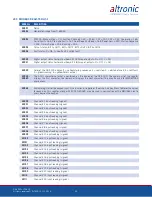
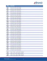
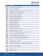
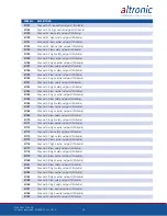
23.0 MODBUS FUNCTIONALITY
23.1 The DE-3000+ is compliant to the Modicon Modbus RTU standard. The data
is duplicated for the 30000’s and 40000’s address range. The maximum
number of registers that can be read at one time has been limited to 32. Only
Modbus function 06 is supported for writing, and unless otherwise noted in
the Modbus Register List, the DE-3000+ only supports register reads. Reg-
isters outside of the defined list are reserved and should not be written to, to
avoid undesired and potentially hazardous effects on the annunciator system.
Содержание DE-3000+ Series
Страница 71: ...DE 3000 IOI 8 15 All rights reserved ALTRONIC LLC 2015 71 FIG 2 DE 3000 SYSTEM DIAGRAM DE 3000 ...
Страница 74: ...DE 3000 IOI 8 15 All rights reserved ALTRONIC LLC 2015 74 FIG 5 WIRING DIAGRAM PERSONAL COMPUTER ...
Страница 75: ...DE 3000 IOI 8 15 All rights reserved ALTRONIC LLC 2015 75 FIG 6 WIRING DIAGRAM SENSOR AND TRANSDUCER INPUTS ...
Страница 76: ...DE 3000 IOI 8 15 All rights reserved ALTRONIC LLC 2015 76 FIG 7 WIRING DIAGRAM CURRENT LOOP OUTPUTS ...
Страница 77: ...DE 3000 IOI 8 15 All rights reserved ALTRONIC LLC 2015 77 FIG 8 WIRING DIAGRAM DIGITAL OUTPUT SWITCHES ...