


DE-3000+ IOI 8-15
All rights reserved © ALTRONIC, LLC 2015
40
13.5 The PRIMARY control input should be selected on the basis of the prevailing operat-
ing conditions at the compressor site as well as considerations of loading fluctua-
tions, etc. Some basic approaches to compressor load control are listed below:
Suction pressure control
By holding suction pressure at a nearly constant value, a large number of limited
flow rate wells can be kept productive with minimal upset conditions. Usually
this approach is characterized as a relatively limited supply, or a low flow rate
supply of gas, at a given site. This approach may also be required as part of
various reclamation or vapor recovery programs. This is an inverse acting re-
lationship — increasing the throughput of the compressor causes the suction
pressure to decrease.
Discharge pressure control
By holding discharge pressure at a constant value, a trunk line feeding a larger
compressor, or pipeline system, permits a supply of gas to be delivered at a rate
approximately equal to the rate at which it is to be consumed. The amount of gas
being compressed is not necessarily limited by its availability at the compres-
sor site, but by how much has been consumed by the destination site. This is a
direct acting relationship — increasing the throughput of the compressor causes
the suction pressure to increase.
Engine Manifold pressure control
By adjusting the compressor throughput on the basis of engine manifold pressure,
compressed gas is being produced at a rate that is determined by the horsepower
available at the site. This approach would be used where there is plenty of gas
available at the wellhead and all of it that is produced can be sold or consumed.
In this situation, the only limitation on compressor loading is how much work the
engine can do without subjecting it or the compressor to an overload. In the case
of electric motor driven compressors, a motor current sensor or kW sensor works
in the same manner as the engine manifold pressure sensor on a gas engine.
13.6 When programming the DE-3000+ system, the basic relationship of the Primary
Control Inputs (CH1, CH2, S01), Primary Control Outputs (AO1 and AO2), and
Output Actuators needs to be defined.
The relationship between a Primary Control Input and Primary Control Output is
defined as either direct or inverse acting. Direct acting means that to increase
the value of the Primary Control Input, the throughput of the compressor is in-
creased. Inverse acting means that to increase the value of the Primary Control
Input, the compressor load must be decreased. In the examples of common
control approaches given; discharge pressure and engine manifold pressure or
motor amps are direct acting. Suction pressure is an example of a control pa-
rameter that is inverse acting. In order to increase suction pressure the com-
pressor throughput must be reduced.
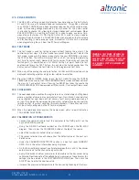
13.7 The secondary control setpoint options have been modified to add more flex-
ibility as detailed below.
•
INHIBIT AN OUTPUT INCREASE
The output of one or more of the control loops can be limited in the increasing
direction only, while allowing the assigned out-put to freely decrease.
•
INHIBIT AN OUTPUT DECREASE
The output of one or more of the control loops can be limited in the decreasing
direction only, while allowing the assigned output to freely increase.
•
FORCE AN OUTPUT INCREASE
The output of one or more of the control loops can be forced to increase even
if the primary control loop requires a different action.
•
FORCE AN OUTPUT DECREASE
The output of one or more of the control loops can be forced to decrease even
if the primary control loop requires a different action.
In addition to these actions being assignable to the analog inputs, they are also assign-
able to the analog outputs (AO1, AO2). This allows for the output of one control loop
to interact with the other according to a programmed priority. For example, the output
of Loop #2 can be inhibited until a certain output value of Loop #1 is reached.
Содержание DE-3000+ Series
Страница 71: ...DE 3000 IOI 8 15 All rights reserved ALTRONIC LLC 2015 71 FIG 2 DE 3000 SYSTEM DIAGRAM DE 3000 ...
Страница 74: ...DE 3000 IOI 8 15 All rights reserved ALTRONIC LLC 2015 74 FIG 5 WIRING DIAGRAM PERSONAL COMPUTER ...
Страница 75: ...DE 3000 IOI 8 15 All rights reserved ALTRONIC LLC 2015 75 FIG 6 WIRING DIAGRAM SENSOR AND TRANSDUCER INPUTS ...
Страница 76: ...DE 3000 IOI 8 15 All rights reserved ALTRONIC LLC 2015 76 FIG 7 WIRING DIAGRAM CURRENT LOOP OUTPUTS ...
Страница 77: ...DE 3000 IOI 8 15 All rights reserved ALTRONIC LLC 2015 77 FIG 8 WIRING DIAGRAM DIGITAL OUTPUT SWITCHES ...