DE-3000+ IOI 8-15
All rights reserved © ALTRONIC, LLC 2015
8
6.5 TEMPERATURE TRANSDUCER
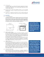
Mount the temperature transducer in a thermowell on the engine or machine.
The actual sensor is located at the bottom of the transducer body; to ensure
accuracy, the tip of the probe should be surrounded by the measured media.
7.0 WIRING
(SEE WIRING DIAGRAMS)
7.1
SYSTEM COMPONENT WIRING
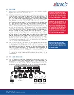
A DB-25 male/female cable, 693115-x series or equivalent, is used to connect
the Terminal Module to the Computer Module and secured with the cable lock
screws. If mounted on the same mounting rail, plug the Terminal Module directly
into the Power Supply Module using the DB-25 D-Sub connectors at the ends
of the modules and secure them together with the screws and screw locks cap-
tive to the connectors. If the Power Supply Module and the Terminal Module are
mounted separate from each other (must be mounted in the same panel) a DB-25
male/female cable such as P/N 693115-1 or equivalent is used to connect these
modules. The HMI connects to the computer module through a CAT E5 cable.
7.2 Connect the supply power wires to the 10-32V input power terminals on the
computer board. Connect the ‘+’ to the ‘DC+’ and connect the ‘-’ to the ‘DC-’
input. Do not connect any other wires into the green Phoenix module. The power
rating for the computer module is 10-32V, .2A Max.
7.2
POWER SUPPLY WIRING
Connect the supply power wires to the 12-24Vdc input power terminals on the
power supply, plus to terminal (+) and minus to terminal (−); power requirement
is 12 to 24Vdc (10 watts max.). The DC− terminal must be connected to panel
ground which should be the same as engine ground.
This is the return path for normally-open sensors and
MUST
be connected for
proper operation.
DO NOT
ground this device directly to the ignition system
common coil ground.
7.3
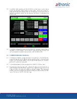
CONNECTING THE 10" MIDAS HMI TO EARTH GROUND
The third pin of the power connector is chassis ground for the unit. The unit
should be connected to earth ground (protective earth).
The chassis ground is not connected to signal common of the unit. Maintaining
isolation between earth ground and signal common is not required to operate
the unit. But, other equipment connected to this unit may require isolation be-
tween signal common and earth ground. To maintain isolation between signal
common and earth ground, care must be taken when connections are made. For
example, a power supply with isolation between its signal common and earth
ground must be used. Also, plugging in a USB cable may connect signal com-
mon and earth ground. The USB’s shield may be connected to earth ground at
the host. USB’s shield, in turn, may also be connected to signal common.
7.4
10" MIDAS HMI POWER SUPPLY REQUIREMENTS
The MIDAS HMI panel requires a 24 VDC power supply. The unit may draw con-
siderably less than the maximum rated power depending upon the features be-
ing used. As additional features are used the unit will draw increasing amounts
of power. Items that could cause increases in current are modules, additional
on-board communications, SD card, and other programmed features.
In any case, it is very important that the power supply is mounted correctly if the
unit is to operate reliably. Please take care to observe the following points:
•
The power supply must be mounted close to the unit, with usually not
more than 6 feet (1.8 m) of cable between the supply and the operator
interface. Ideally, the shortest length possible should be used.
•
The wire used to connect the operator interface’s power supply should
be at least 22-gage wire suitably rated for the temperatures of the
environment to which it is being installed. If a longer cable run is used,
a heavier gage wire should be used. The routing of the cable should be
kept away from large contactors, inverters, and other devices which may
generate significant electrical noise.
IMPORTANT: DO NOT EXCEED THE
ABSOLUTE MAXIMUM RATING OF THE
TRANSDUCERS, 350°F (176°C) FOR THE
691202/203-300 OR 450°F (232°C) FOR
THE 691212/213-450. CARE SHOULD
BE TAKEN TO PROTECT THE WIRING AND
CONNECTORS FROM CONTACT WITH HOT
SURFACES.
Содержание DE-3000+ Series
Страница 71: ...DE 3000 IOI 8 15 All rights reserved ALTRONIC LLC 2015 71 FIG 2 DE 3000 SYSTEM DIAGRAM DE 3000 ...
Страница 74: ...DE 3000 IOI 8 15 All rights reserved ALTRONIC LLC 2015 74 FIG 5 WIRING DIAGRAM PERSONAL COMPUTER ...
Страница 75: ...DE 3000 IOI 8 15 All rights reserved ALTRONIC LLC 2015 75 FIG 6 WIRING DIAGRAM SENSOR AND TRANSDUCER INPUTS ...
Страница 76: ...DE 3000 IOI 8 15 All rights reserved ALTRONIC LLC 2015 76 FIG 7 WIRING DIAGRAM CURRENT LOOP OUTPUTS ...
Страница 77: ...DE 3000 IOI 8 15 All rights reserved ALTRONIC LLC 2015 77 FIG 8 WIRING DIAGRAM DIGITAL OUTPUT SWITCHES ...


