DE-3000+ IOI 8-15
All rights reserved © ALTRONIC, LLC 2015
39
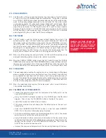
12.4 The engine speed must also reach a speed above the Crank/Multi-Start discon-
nect RPM before its corresponding timer expires. If it does not, an OVERCRANK
FAULT will be generated and all outputs will turn OFF. If the DE-3000+ is set up
for Multi-Start, then a delay timer will begin counting down before another start
attempt is automatically triggered. Pressing any button on the display during
the time between start attempts will cancel Multi-Start, and the DE-3000+ will
remain in a Stop/Fault mode until it is manually restarted.
12.5 The Auxiliary and Start/Run Signal turn ON once their corresponding ‘Delay be-
fore ON’ timers expire. The Auxiliary output will remain on for the entirety of the
DE’s run time, but the Start/Run Signal can be programmed to turn OFF after
1-5 seconds, or just remain ON during the DE’s run time.
12.6 When a manual stop or fault occurs, DER turns OFF and Lube turns ON. The
Auxiliary and Start/Run Signal (if still ON) remain ON after a stop or fault for
their respective ‘Hold after Stop’ times and then turn OFF. Lube turns OFF after
its programmed Post Lube time.
13.0 SELECTING A CONTROL STRATEGY
13.1 The control strategy best suited to a particular application varies widely. The fol-
lowing information is offered as a set of general guidelines and definitions. Each
application should be evaluated by qualified personnel familiar with the actual
operating conditions.
13.2 The DE-3000+ controller can be programmed to regulate compressor throughput
by controlling both capacity and engine speed. In any particular application, it may
be desirable to control the total compressor throughput using only one of these.
13.3 The RPM control of the engine can be done using one of the analog control out-
puts of the DE-3000+ as a 4-20mA current loop which can be connected directly
to an electronic governor. If a governor requiring a pneumatic setpoint (3-15psi) is
used then the 4-20mA output is connected to an appropriate I/P transducer.
13.4 The CAPACITY control output of the DE-3000+ is available in two formats, to
drive the most common actuating systems. The first output format is an indus-
try-standard 4-20mA current loop used for continuously adjustable (sometimes
referred to as linear) control. The 4-20mA output would typically be used to
interface to a pneumatically controlled bypass valve. A second set of capacity
control outputs is brought out of the controller in a digital format (discrete tran-
sistors). The digital or discrete outputs consist of two transistors which switch
on to ground and are designed to drive relay coils or pilot duty solenoid valves.
One switch is labeled DIGITAL OUT 1 and energizes to LOAD the compressor
the other is labeled DIGITAL OUT 2 and energizes to UNLOAD the compressor.
The typical application on reciprocating compressors would be to use the
4-20mA. CAPACITY output to connect to an appropriate I/P transducer which
then connects via tubing to the actuator input of a pneumatically controlled
external bypass valve.
On some screw compressors utilizing an internal stepless bypass, a spring-bi-
ased turn valve, or slide valve, the 4-20mA. CAPACITY output can be connected
to an appropriate I/P transducer which then connects via tubing to the actuator
in order to move the valve
The second set of capacity control outputs is brought out of the controller in
a digital format (discrete transistors). The digital or discrete outputs consist of
two transistors which switch on to ground and are designed to drive relay coils or
pilot duty solenoid valves. One switch is labeled DIGITAL OUT 1 and energizes
to LOAD the compressor the other is labeled DIGITAL OUT 2 and energizes to
UNLOAD the compressor. When used with the hydraulically positioned slide
valve on a screw compressor application, these outputs are typically connected
to a three-way solenoid valve. On reciprocating compressors, the digital outputs
can be used to actuate a motor controlled bypass valve via relay contacts which
energize the motor to move in the open or close directions.
Содержание DE-3000+ Series
Страница 71: ...DE 3000 IOI 8 15 All rights reserved ALTRONIC LLC 2015 71 FIG 2 DE 3000 SYSTEM DIAGRAM DE 3000 ...
Страница 74: ...DE 3000 IOI 8 15 All rights reserved ALTRONIC LLC 2015 74 FIG 5 WIRING DIAGRAM PERSONAL COMPUTER ...
Страница 75: ...DE 3000 IOI 8 15 All rights reserved ALTRONIC LLC 2015 75 FIG 6 WIRING DIAGRAM SENSOR AND TRANSDUCER INPUTS ...
Страница 76: ...DE 3000 IOI 8 15 All rights reserved ALTRONIC LLC 2015 76 FIG 7 WIRING DIAGRAM CURRENT LOOP OUTPUTS ...
Страница 77: ...DE 3000 IOI 8 15 All rights reserved ALTRONIC LLC 2015 77 FIG 8 WIRING DIAGRAM DIGITAL OUTPUT SWITCHES ...


