


DE-3000+ IOI 8-15
All rights reserved © ALTRONIC, LLC 2015
7
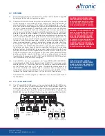
5.9
4-20mA inputs
The terminal module can accept 4-20mA inputs by selecting the internally-
connected 200-ohm resistors, creating a termination voltage of .8 to 4.0 volts.
The jumper wires between the + and – terminals for that channel must be con-
nected for proper operation.
5.10 For each input, the corresponding CHANNEL SWITCH must be set according
to the input type. Switches are turned ON by moving them toward the ANALOG
OUT labeling.
5.11 Digital outputs 1 through 8 are pilot-duty, and turn on to common ground when
closed. Outputs 1 through 8 are rated at 500mA, 60V. See FIG. 8 for wiring details.
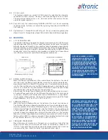
6.0 MOUNTING
6.1
10" COLOR MIDAS HMI
The operator interface is designed for through-panel mounting. Four VESA mount
tapped screw-holes (M4 x 0.7, 5 mm deep) are present on the rear of the panel to
allow for stand or wall mounting. Care should be taken to remove any loose material
from the mounting cut-out to prevent that material from falling into the operator in-
terface during installation. A gasket is provided to enable sealing to NEMA 4X/IP66
specification. Install the mounting clips provided and tighten to 6.0 pound-force
inch (96 ounce-force inch) evenly for uniform gasket compression.
6.2 POWER SUPPLY MODULE
Mount the Power Supply Module in the panel either on the bottom or the side of
the main panel. The Power Supply Module is made to be rail-mounted onto com-
mercially available 32 or 35mm DIN mounting rails. It is also made to plug directly
into the Terminal Module using the DB-25 connectors and is held together with
screws and screw locks. Two end brackets P/N 604199 should be used to keep
the modules from sliding off the ends of the mounting rail.
Alternatively, the Power Supply Module and the Terminal Module can be mount-
ed separate from each other on the DIN mounting rails but in the same panel;
in this case, a DB-25 male/female cable such as P/N 693115-1 is used to elec-
trically connect these modules. The operating temperature range of the Power
Supply Module is −31°F to +176°F (−35°C to +80°C).
6.3 TERMINAL MODULE
Mount the Terminal Module either on the bottom or the side of the main panel.
The Terminal Module and Power Supply Module can be rail-mounted onto com-
mercially available 32 or 35mm DIN mounting rails. The Terminal Module plugs
directly into the Power Supply Module using the DB-25 D-Sub connectors and
is held together with screws and screw locks. Two end brackets P/N 604199
are used to keep the modules from sliding off the ends of the rail. The Terminal
Module and the Display Module are electrically connected with a DB-25 male/
female cable, 693115-x series or equivalent. The operating temperature range
of the Terminal Module is −31°F to +176°F (−35°C to +80°C).
6.4 PRESSURE TRANSDUCER
Mount the pressure transducer in the panel or in a manifold or tube off of the
engine. Do not expose the pressure transducer to temperatures above 221°F
(105°C). The second terminal module should be placed close to the first and the
wire connecting them should be free of high-powered panel signals.
NOTE: FOR HAZARDOUS LOCATION
INSTALLATION, THIS DEVICE MUST BE
MOUNTED IN A SUITABLE DUST TIGHT
END-ENCLOSURE AND MUST BE WIRED
USING DIVISION 2 WIRING METHODS AS
SPECIFIED IN ARTICLE 501-4 (B), 502-4
(B), AND 503-3 (B) OF THE NATIONAL
ELECTRICAL CODE, NFPA 70 FOR INSTAL-
LATION WITHIN THE UNITED STATES, OR
AS SPECIFIED IN SECTION 19-152 OF
CANADIAN ELECTRICAL CODE FOR INSTAL-
LATION IN CANADA.
IMPORTANT: PRESSURE TRANSDUCERS
WILL WITHSTAND OVERLOADS AS HIGH
AS 1.5 TIMES RATED PRESSURE. IF THE
OVERLOAD RATING IS EXCEEDED, FAIL-
URE MAY OCCUR. PRESSURE FLUCTUA-
TIONS OCCUR IN MOST RECIPROCATING
SYSTEMS; PICK THE TRANSDUCER
WITH A RATING HIGH ENOUGH TO PRE-
VENT OVERLOAD BY PEAK PRESSURES
OF PULSATIONS. IT IS RECOMMENDED
THAT A PRESSURE SNUBBER BE USED
WHICH WILL REDUCE THE PEAK PRES-
SURE APPLIED TO THE TRANSDUCER.
THE LIFE OF THE TRANSDUCER WILL BE
EXTENDED WITH THE USE OF A SNUB-
BER OR PULSATION DAMPENER.
Содержание DE-3000+ Series
Страница 71: ...DE 3000 IOI 8 15 All rights reserved ALTRONIC LLC 2015 71 FIG 2 DE 3000 SYSTEM DIAGRAM DE 3000 ...
Страница 74: ...DE 3000 IOI 8 15 All rights reserved ALTRONIC LLC 2015 74 FIG 5 WIRING DIAGRAM PERSONAL COMPUTER ...
Страница 75: ...DE 3000 IOI 8 15 All rights reserved ALTRONIC LLC 2015 75 FIG 6 WIRING DIAGRAM SENSOR AND TRANSDUCER INPUTS ...
Страница 76: ...DE 3000 IOI 8 15 All rights reserved ALTRONIC LLC 2015 76 FIG 7 WIRING DIAGRAM CURRENT LOOP OUTPUTS ...
Страница 77: ...DE 3000 IOI 8 15 All rights reserved ALTRONIC LLC 2015 77 FIG 8 WIRING DIAGRAM DIGITAL OUTPUT SWITCHES ...