


DE-3000+ IOI 8-15
All rights reserved © ALTRONIC, LLC 2015
9
•
A power supply with an NEC Class 2 or Limited Power Source (LPS) and
SELV rating is to be used. This type of power supply provides isolation to
accessible circuits from hazardous voltage levels generated by a mains
power supply due to single faults. SELV is an acronym for “safety extra-
low voltage.” Safety extra-low voltage circuits shall exhibit voltages safe
to touch both under normal operating conditions and after a single fault,
such as a breakdown of a layer of basic insulation or after the failure of
a single component has occurred. A suitable disconnect device shall be
provided by the end user.
7.5
SENSOR WIRING DISCRETE INPUTS
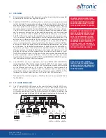
The sensor leads connect to the removable terminal strips on the Terminal Mod-
ule. The terminal numbers correspond to the display numbers which also have a
user assigned 20-character label associated with it. The sensor inputs are num-
bered 01-30, 01-45 or 01-60. With AUTO START enabled, the Remote Reset
on the terminal board is wired for a start switch. Sensor inputs 01–60 can be
configured as class A, class B or class C logic. Any discrete sensor point can be
wired for normally-open or normally-closed operation.
•
Normally-open (N/O) sensor switches are wired with one wire to the
bottom terminal strip of the respective sensor number and the other to
engine ground which should be the same as power minus (−). A short
jumper from the bottom terminal to the top terminal must be connected
for normally-open sensors. (See wiring diagrams)
•
Normally-closed (N/C) sensor switches are wired with one wire to the bot-
tom terminal strip and the other to the top terminal strip of the respective
sensor number. Note that the short jumper wire must be removed.
•
Remote stop and remote reset are wired the same as the sensor
switches, and can be used with either normally-open or normally-closed
contacts.
Use a wire size between 16 AWG (max.) and 24 AWG (min.) to connect the sen-
sor switches to the terminal strip connector. Strip the insulation back 3/8"; twist
the exposed wires tightly together. Insert the exposed wire completely into the
terminal strip and securely tighten the clamping screw. Wires running to sensor
switches must be in good condition or replaced with new wires. When running
wires, take care not to damage the insulation and take precautions against later
damage from vibration, abrasion, or liquids in conduits. An explosion-proof con-
duit is not required. However; wires should be protected from damage by run-
ning them in a protective conduit or in sheaths where appropriate. In addition, it
is essential that the following practices be adhered to:
A. Never run sensor wires in the same conduit with ignition wiring or other
high energy wiring such as the AC line power.
B. Keep secondary wires to spark plugs and other high voltage wiring at
least eight inches (200mm) away from sensor and sensor wiring.
C. Sensor switches may be connected to any passive device using contacts
such as standard switch gauges, pressure or level switches.
DO NOT
con-
nect sensor leads to any voltage producing element.
D. In the case of a field conversion, where sensors have previously been
used with Murphy tattletales, it is recommended that the sensors be
checked frequently when the DE system is first put into use. Sensor
contacts may be burned or pitted from past exposure to ignition system
primary voltage. It is advisable to replace such sensors.
E. If it becomes necessary to check sensor switch to panel wiring with an
ohmmeter or other checker, first DISCONNECT the plug-in terminal strips
from the Terminal Module. Applying voltage to the DE-3000+ system
through the sensor leads may damage the device. The area should be
tested as non-hazardous before such testing commences.
Содержание DE-3000+ Series
Страница 71: ...DE 3000 IOI 8 15 All rights reserved ALTRONIC LLC 2015 71 FIG 2 DE 3000 SYSTEM DIAGRAM DE 3000 ...
Страница 74: ...DE 3000 IOI 8 15 All rights reserved ALTRONIC LLC 2015 74 FIG 5 WIRING DIAGRAM PERSONAL COMPUTER ...
Страница 75: ...DE 3000 IOI 8 15 All rights reserved ALTRONIC LLC 2015 75 FIG 6 WIRING DIAGRAM SENSOR AND TRANSDUCER INPUTS ...
Страница 76: ...DE 3000 IOI 8 15 All rights reserved ALTRONIC LLC 2015 76 FIG 7 WIRING DIAGRAM CURRENT LOOP OUTPUTS ...
Страница 77: ...DE 3000 IOI 8 15 All rights reserved ALTRONIC LLC 2015 77 FIG 8 WIRING DIAGRAM DIGITAL OUTPUT SWITCHES ...