


June 2012
Altera Corporation
Stratix V Hard IP for PCI Express
Additional Information
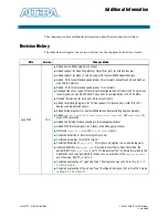
This chapter provides additional information about the document and Altera.
Revision History
The table below displays the revision history for the chapters in this User Guide.
Date
Version
Changes Made
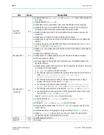
June 2012
12.0
■
Added Avalon-MM single dword variant.
■
Added support for Gen3 Programmer Object File (.pof) for Stratix V devices.
■
Added support for Gen3 ×1 and ×4 support for Avalon-MM Endpoint designs.
■
Added -C4 to recommended speed grades for all variants except Gen3 ×8 and Gen3 ×4
with 128-bit interface.
■
Added -C1 to recommended speed grades for all variants.
■
Changed frequency range of Transceiver Reconfiguration Controller clock. The previous
recommendation was 90-100 MHz. The current recommendation is 100-125 MHz.
■
Revised illustrations for hard and soft reset controllers.
■
Added reset timing diagrams for TX transceivers, RX transceivers, Hard IP for PCI
Express and Application Layers.
■
Added timing diagrams for Avalon-MM interface demonstrating duplex operation.
■
Added
txblkst
,
txsychd0
,
txdataskip
,
rxblkst
,
rxsychd0
, and
rxdataskip
for
Gen3 PIPE simulation.
■
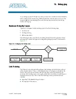
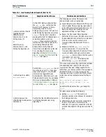
Added link training trouble-shooting to the
Debugging
chapter.
■
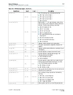
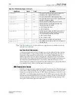
Added PIPE interface signals for 2 lanes to the
Debugging
chapter.
■
Removed
fixedclk_locked
and
cfg_link2csr
signals.
■
Corrected definition of flow control protocol error.
■
Corrected encodings for rate[1:0] signal.
■
Corrected definition of
cpl_err[2]
. This signal only applies to non-posted requests.
■
Updated definition of
app_msi_req
to include the fact that in Root Port mode, the
header bit[127] of
rx_st_data
is set to 1 to indicate that the TLP being forwarded to the
Application Layer was generated in response to an assertion of the
app_msi_request
pin; otherwise, bit[127] is set to 0.
■
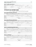
Corrected explanation of Type 0 and Type 1 Configuration Space TLPs in
■
Corrected explanation of Type 0 and Type 1 Configuration Space TLPs in Root Port mode
in