


Chapter 15: Debugging
15–3
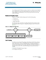
Link Training
June 2012
Altera Corporation
Stratix V Hard IP for PCI Express
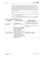
Link fails with the LTSSM
toggling between:
Detect.Quiet (0),
Detect.Active (1), and
Polling.Active (2),
or:
Detect.Quiet (0),
Detect.Active (1), and
Polling.Configuration (4)
On the PIPE interface extracted from
the
test_out
bus, confirm that the
Hard IP for PCI Express IP Core is
transmitting valid TS1 in the
Polling.Active(2) state or TS1 and TS2
in the Polling.Configuration (4) state on
txdata0
. The Root Port should be
sending either the TS1 Ordered Set or a
compliance pattern as seen on
rxdata0
. These symptoms indicate
that the Root Port did not receive the
valid training Ordered Set from
Endpoint because the Endpoint
transmitted corrupted data on the link.
You can debug this issue using
SignalTap II. Refer to
for a list of the
test_out
bus signals.
The following are some of the reasons the
Endpoint might send corrupted data:
■
Signal integrity issues. Measure the TX eye and
check it against the eye opening requirements
in the
PCI Express Base Specification, Rev 3.0.
Adjust the transceiver pre-emphasis and
equalization settings to open the eye.
■
Bypass the Transceiver Reconfiguration
Controller IP Core to see if the link comes up at
the expected data rate without this component.
If it does, make sure the connection to
Transceiver Reconfig Controller IP Core is
correct.
■
Make sure that the
busy_xcvr_reconfig
signal is deasserted. If it is asserted, the
Transceiver Reconfiguration Controller IP Core
reset is not debounced and synchronized to
reconfig_clk
domain. Check that the system
reset sequence to waits for
busy_xcvr_reconfig
to be deasserted
before taking
pin_perst
out of reset.
Link fails due to unstable
rx_signaldetect
Confirm that
rx_signaldetect
bus of
the active lanes is all 1’s. If all active
lanes are driving all 1’s, the LTSSM
state machine toggles between
Detect.Quiet(0), Detect.Active(1), and
Polling.Active(2) states. You can debug
this issue using SignalTap II. Refer to
“PIPE Interface Signals” on page 15–6
for a list of the
test_out
bus signals.
This issue may be caused by mismatches between
the expected power supply to RX side of the
receiver and the actual voltage supplied to the
FPGA from your boards. Stratix V devices require
VCCR/VCCT to be 1.0 V. You must apply the
following command to both P and N pins of each
active channel to override the default setting of
0.85 V.
set_instance_assignment -name
XCVR_VCCR_VCCT_VOLTAGE 1_0V –to
“pin”
Substitute the pin names from your design for
“pin”
.
Link fails because the
LTSSM state machine enters
Compliance
Confirm that the LTSSM state machine
is in Polling.Compliance(3) using
SignalTap II.
Possible causes include the following:
■
Setting
test_in[6]
=1 forces entry to
Compliance mode when a timeout is reached in
the Polling.Active state.
■
Differential pairs are incorrectly connected to
the pins of the device. For example, the
Endpoint’s TX signals are connected to the RX
pins and the Endpoint’s RX signals are to the TX
pins.
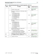
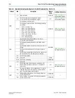
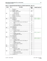
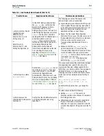
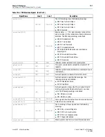
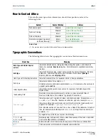
Table 15–1. Link Training Fails to Reach L0 (Part 2 of 3)
Possible Causes
Symptoms and Root Causes
Workarounds and Solutions