


6–28
Chapter 6: IP Core Interfaces
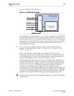
Clock Signals
Stratix V Hard IP for PCI Express
June 2012
Altera Corporation
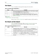
Clock Signals
describes the clock signals that comprise the clock interface.
Refer to
for a complete description of the clock interface.
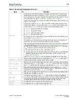
Reset Signals and Status Signals
describes the reset signals. Refer to
information about the reset sequence and a block diagram of the reset logic.
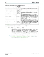
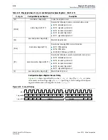
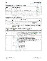
Table 6–6. Clock Signals Hard IP Implementation
Signal
I/O
Description
refclk
I
Reference clock for the Stratix V Hard IP for PCI Express. It must have the frequency specified
under the
System Settings
heading in the parameter editor.
pld_clk
I
Clocks the Application Layer. You must drive this clock from
coreclkout_hip
.
coreclkout_hip
O
This is a fixed frequency clock used by the Data Link and Transaction Layers. To meet PCI
Express link bandwidth constraints, this clock has minimum frequency requirements as listed
in
.
Note to
(1)
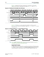
illustrates these clock signals.
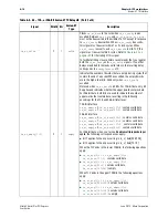
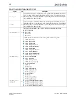
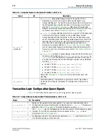
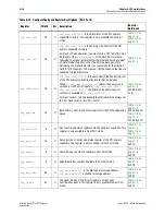
Table 6–7. Reset and Link Training Signals (Part 1 of 3)
Signal
I/O
Description
npor
I
Active low reset signal. It is the
OR
of
pin_perst
and
local_rstn
coming from the
software Application Layer. If you do not drive a soft reset signal from the Application Layer,
this signal must be derived from
pin_perst
. You cannot disable this signal. Asynchronous.
Resets the entire Stratix V Hard IP for PCI Express IP Core and transceiver.
reset_status
O
Active high reset status signal. When asserted, this signal indicates that the Hard IP clock is
in reset. The
reset_status
signal is synchronous to the
pld_clk
clock and is deasserted
only when the
npor
is deasserted and the Hard IP for PCI Express is not in reset
(
reset_status_hip
= 0). You should use
reset_status
to drive the reset of your
application.