


6–46
Chapter 6: IP Core Interfaces
Power Management Signals
Stratix V Hard IP for PCI Express
June 2012
Altera Corporation
Power Management Signals
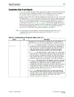
describes the power management signals.
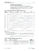
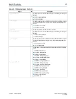
shows the layout of the Power Management Capabilities register.
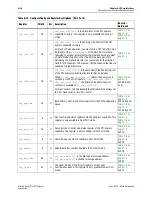
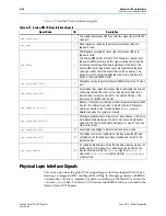
Table 6–21. Power Management Signals
Signal
I/O
Description
pme_to_cr
I
Power management turn off control register.
Root Port—When this signal is asserted, the Root Port sends the
PME_turn_off
message.
Endpoint—This signal is asserted to acknowledge the
PME_turn_off
message by sending
pme_to_ack
to the Root Port.
pme_to_sr
O
Power management turn off status register.
Root Port—This signal is asserted for 1 clock cycle when the Root Port receives the
pme_turn_off
acknowledge message.
Endpoint—This signal is asserted for 1 cycle when the Endpoint receives the
PME_turn_off
message from the Root Port.
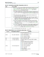
pm_event
I
Power Management Event. This signal is only available for Endpoints.
The Endpoint initiates a a
power_management_event
message (PM_PME) that is sent to
the Root Port. If the Hard IP is in a low power state, the link exists from the low-power state
to send the message. This signal is positive edge-sensitive.
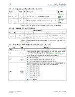
pm_data[9:0]
I
Power Management Data.
This bus indicates power consumption of the component. This bus can only be
implemented if all three bits of
AUX_power
(part of the Power Management Capabilities
structure) are set to 0. This bus includes the following bits:
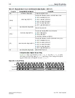
■
pm_data[9:2]
: Data Register: This register maintains a value associated with the power
consumed by the component. (Refer to the example below)
■
pm_data[1:0]
: Data Scale: This register maintains the scale used to find the power
consumed by a particular component and can include the following values:
■
2b’00: unknown
■
2b’01: 0.1 ×
■
2b’10: 0.01 ×
■
2b’11: 0.001 ×
For example, the two registers might have the following values:
■
pm_data[9:2]
: b’1110010 = 114
■
pm_data[1:0]
: b’10, which encodes a factor of 0.01
To find the maximum power consumed by this component, multiply the data value by the
data Scale (114 × .01 = 1.14). 1.14 watts is the maximum power allocated to this
component in the power state selected by the
data_select
field.
pm_auxpwr
I
Power Management Auxiliary Power: This signal can be tied to 0 because the L2 power
state is not supported.
Table 6–22. Power Management Capabilities Register
31
24
22
16
15
14
13
12
9
8
7
2
1
0
data
register
rsvd
PME_status
data_scale
data_select
PME_EN
rsvd
PM_state