background image


15

14.0 Operation 

  Mow only in daylight or in good artificial light 

  Where feasible,  avoid  operating  the mower  in  wet  grass  where  traction  may 

be compromised.  

  Walk, never run. 

  The  ELMOW  mower  is  designed  for  fine  turf  applications  where  there  is  a 

small  likelihood  of  encountering  steep  slopes.  Excessively  steep  slopes 
should be avoided, however, always be sure of your footing and use extreme 
caution when changing direction on slopes. 

  Use extreme caution when reversing the lawnmower. 

  Always disengage the drive to the cylinder before travelling over any surface 

other than grass and when transporting the mower to and from the area to be 
mowed. 

  When  using  the  mower,  never  direct  the  discharged  material  towards 

bystanders or allow anyone near the machine whilst it is in operation. 

  Never operate a mower with defective guards, or without the grass deflectors 

and grass box.  

  Do  not  attempt  to  increase  the  factory  set  maximum  speed  of  the  motors. 

Operating at an excessive speed can increase the hazard of personal injury. 

  Switch  on  the  motor  carefully  according  to  the  instructions  and  keep  hands 

and feet well away from the blades. 

  Do not tilt the mower when starting the motors. 

  Do  not  start  the  motors  when  any  one  is  standing  in  front  of  the  discharge 

opening. 

  Do  not  put  hands  or  feet  near  or  under  rotating  parts.  Keep  clear  of  the 

discharge openings at all times. 

  Never pick up or carry the mower while the motors are running. 

  Do  not  put  hands  or  feet  near  rotating  parts  while  the  lawnmower  is  being 

operated 

  After striking a foreign object remove the battery isolation key and inspect the 

mower for damage, make repairs before restarting and operating the mower. 

  Never operate equipment that is missing guarding, decals or is not operating 

properly. 

  Never interfere with or bypass the action of any switch. 

Содержание ELMOW 20

Страница 1: ...rsion Turfmech Machinery Limited Hangar 5 New Road Hixon Stafford ST18 0PJ United Kingdom Tel 44 0 1889 271503 Fax 44 0 1889 271321 Sales turfmech co uk www turfmech co uk For Allett spare parts Tel 44 0 1889 272095 Fax 44 0 1889 271321 Sales allett co uk www allett co uk ...

Страница 2: ...2 ATTENTION THIS SYMBOL MEANS BE ALERT YOUR SAFETY IS INVOLVED READ THIS MANUAL BEFORE USING AN ALLETT ELMOW CYLINDER MOWER IT IS ESSENTIAL THAT OPERATORS STUDY IT FOR THEIR OWN SAFETY ...

Страница 3: ...ward speed and Clip rate 13 10 5 Chain and belt tension 13 10 6 Handle bar height 14 11 0 Safe operating practices 14 12 0 Training 14 13 0 Preparation 14 14 0 Operation 15 15 0 Batteries 16 16 0 Maintenance and storage 17 16 1 Inspection of critical safety components 17 16 2 Maintenance Schedule 18 16 3 Checking the cutting cylinder 19 16 4 Storage 19 16 5 Cleaning the mower 19 17 0 Options Kick ...

Страница 4: ...e and repair as specified in this manual also constitute essential elements of the intended use The way in which the ELMOW mower is operated and maintained will have a profound effect on its performance and reliability An ELMOW mower should be operated serviced and repaired only by persons who are familiar with its particular characteristics and who are familiar with the relevant safety procedures...

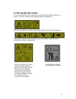
Страница 5: ...efore maintenance Flying debris keep bystanders away Warning sharp blades blades continue to rotate after the mower is switched off Warning take care not to short across the battery terminals when carrying out maintenance Please be environmentally responsible and recycle this product at the end of its life Connect the batteries isolation key ammeter and fuse according to this diagram Guaranteed so...

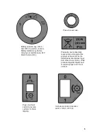
Страница 6: ...ress to reset fuse Please be environmentally responsible and recycle this product at the end of its life 320W peak rated power input 24V Direct Current DC IPX3 protected against liquids and moisture sprays to 60 from vertical Press and hold switch to reverse cylinder for back lapping Cylinder controller activation switch ON 1 OFF 0 ...

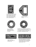
Страница 7: ...e to slow tortoise in three steps Cut height Turning anticlockwise increases cut height turning clockwise decreases cut height 1 audible click moves the front roller by 0 3mm 1 80 this alters the bottom blade height by 0 175mm 7 thousandths of an inch Apply two pumps of grease from a grease gun every fifty hours Bottom blade adjustment turn clockwise to move the bottom blade away from the cutting ...

Страница 8: ... cylinder Prepare to operate the mower refer to the previous section Press one or both of the red operator presence controls to the handle bar Switch ON 1 the cutting cylinder controller activation switch located on the left hand panel Move the small red central switch first to unlatch the main switch for operation Wait for the green light next to the switch to show continuously if it does not see...

Страница 9: ...ation of the throttle control will increase forward speed Maximum speed can be adjusted by the rotary speed switch located on the right hand control panel Turn the dial to select between the three speeds As forward speed is increased by this rotary switch clip rate will automatically increase 8 0 Stopping and charging Turn OFF 0 both the cutting cylinder controller activation switch and the land r...

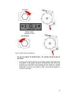
Страница 10: ...nd the cutting cylinder Turn the cutting cylinder slowly by hand If the blade is set properly the paper should cut cleanly along the full length of the cylinder If it does not then proceed as described on the next page Locate the two bottom blade adjusters 1 in Figure 1 The adjusters alter the gap between the bottom blade and the cutting cylinder Rotate the adjusters clockwise to increase the gap ...

Страница 11: ...leanly cut the paper inspect the bottom blade and cylinder If they appear rounded or damaged they may need to be sharpened or back lapped Back lapping involves applying a suitable grinding paste 180 grit to the bottom blade then running the cylinder backwards This hones the cylinder to create a fine tolerance between it and the bottom blade Bottom blade adjustment decal ...

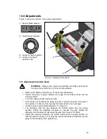
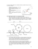
Страница 12: ...l they reach the desired height of cut X and the desired groomer height Y as shown in Figure 4 below Figure 4 Height of cut and groomer depth Once adjusted position the setting bar so that the underside of the bolt head X rests on top of the leading edge of the bottom blade The rearward end of the bar must make contact with the rear roller as shown by Figure 4 above Adjust the height of the front ...

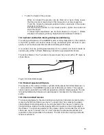
Страница 13: ...lett dealer The bottom blade of the Tournament mower should be ground with a 5O angle as shown below Figure 5 bottom blade angles 10 4 Forward speed and Clip rate The clip rate is the number of times a cylinder blade passes the bottom blade over a 1 metre distance The ELMOW clip rate is set at 246 cuts per metre Three speed options can be selected to suit different operators preferred mowing speed...

Страница 14: ...ructions carefully Be familiar with the controls and the proper use of the equipment Never allow children or people unfamiliar with these operating instructions to use the mower or its attachments Local regulations may restrict the age of the operator Be alert while people especially children or animals are nearby Bear in mind that the operator is responsible for accidents or hazards occurring to ...

Страница 15: ...with defective guards or without the grass deflectors and grass box Do not attempt to increase the factory set maximum speed of the motors Operating at an excessive speed can increase the hazard of personal injury Switch on the motor carefully according to the instructions and keep hands and feet well away from the blades Do not tilt the mower when starting the motors Do not start the motors when ...

Страница 16: ...ce the batteries Turn the battery isolation key to the OFF 0 position Unplug the battery lead from the mower power socket Remove the battery pack from the mower and position on a non conducting surface Wearing suitable safety clothing eye and face protection gloves and long sleeved clothing Remove the battery pack cover Disconnect the wiring to the terminals taking care not to cause any short circ...

Страница 17: ...e worn or damaged parts for safety Be careful during adjustment of the machine to prevent entrapment of the fingers between moving blades and fixed parts of the machine 16 1 Inspection of critical safety components The below components are critical to the safe use of the mower Check they are in good working order regularly Operator presence control levers The cylinder requires two separate operati...

Страница 18: ...d inputs and outputs of the mower Controllers are essential to the safe operating of the mower If the safety functions of the mower do not operate as described in this manual remove the battery isolation key check the wiring then contact your local Allett dealer In case of abnormal vibration stop immediately and remove the battery isolation key Visually check for blockages obstructions or incorrec...

Страница 19: ...te all grease points and apply a thin coat of chain lubricant to the chains Connect the battery pack to the charger 16 5 Cleaning the mower When cleaning the mower NEVER use a pressure washer Use low pressure water or compressed air Always remove the battery isolation key 17 0 Options Kick stand and Transport wheels Where a long distance needs to be covered over non turf surfaces the transport whe...

Страница 20: ...for conditions Increase height of cut Uneven ground conditions Increase height of cut change direction of cut Ribbing of grass perpendicular to direction of travel Forward travel speed too fast Reduce forward travel speed Tram lining of grass in the direction of forward travel Bottom blade in ground contact Poor cylinder to bottom blade adjustment Increase height of cut Re adjust bottom blade Worn...

Страница 21: ...e controller on Ensure the throttle is in neutral when turning the controller on The throttle may require re calibration 7 Throttle or speed selection switch fault The throttle speed selection switch or their associated wiring may be faulty Check the throttle speed selection switch associated wiring and connections 8 Motor voltage fault The motor or its associated wiring is faulty Check the motor ...

Страница 22: ...these factors will affect the operator s daily personal noise exposure level LEP d The guaranteed sound power level is 76 dB A measured in accordance with EC Directive 2000 14 EC and BS EN 836 1997 Setting the cylinder and bottom blade to be non contacting will reduce noise emission A well maintained sharp and accurately ground cylinder and bottom blade are recommended to minimise noise emission 2...

Страница 23: ...2009 Safety of machinery Basic concepts general principles for design Technical principles EN 50338 2006 Safety of household and similar electrical appliances Particular requirements for pedestrian controlled battery powered electric lawn mowers BS EN 836 1997 Garden equipment Powered lawnmowers Safety EN 60335 1 2002 A2 2006 Household and similar electrical appliances Safety Part 1 General requir...

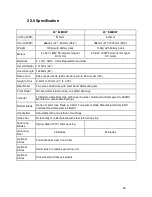
Страница 24: ... aluminium with steel bevel differential gear Front Roller Grooved aluminium running on sealed bearings Cylinder 10 bladed all welded high carbon spring steel hardened and tempered to 45HRC Mounted on greaseable bearings Bottom Blade Option of 4mm face blade or 2 4mm Tournament blade Manufactured from EN11 hardened and tempered to 45HRC Handle Bar Adjustable with anti vibration mountings Grass box...

Страница 25: ...rsion Turfmech Machinery Limited Hangar 5 New Road Hixon Stafford ST18 0PJ United Kingdom Tel 44 0 1889 271503 Fax 44 0 1889 271321 Sales turfmech co uk www turfmech co uk For Allett spare parts Tel 44 0 1889 272095 Fax 44 0 1889 271321 Sales allett co uk www allett co uk ...

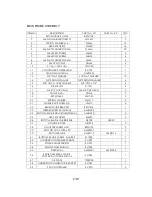
Страница 26: ...4 17 M6 X 12 CAP HEAD M6x12 CAP HEAD 2 18 Nut M6 Nyloc NNM6 9 19 SET M10x25 SM1025 2 20 SPRING WASHER SWM10 2 21 WASHER M10 FORM Z C WM10 2 22 BRUSH GUIDE BRACKET BSG1205 1 23 GREASE EVERY 50H DECAL AM81539 1 24 BOTTOM BLADE ADJUSTMENT DECAL AM81540 2 25 HEX SET SCREW SM620 5 26 BOTTOM BLADE CARRIER FAB AS005 AS032 1 27 ADJUSTER FORK AB1004 2 28 ADJUSTER SCREW ASSY BSG053 2 29 ROLL PIN M10 x MBK x...

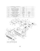
Страница 27: ...PPORT PRESSING EL1057 1 44 BATTERY SLIDE PAD EL1058 1 45 CYLINDER 10 BLADE AM81216 AM81217 1 46 S T DELIVERY PLATE BRACKET BSG1326 BSG1324 1 47 DELIVERY PLATE FAB BSG179 BSG180 1 48 MOTOR CONTROLLER COVER EL1043 1 49 ELMOW 20 CHASSIS EL001 EL013 1 26 31 BOTTOM BLADE CARRIER AND ADJUSTER ASSY AS056 AS061 1 Figure 1 Main frame assembly ...

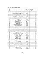
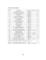
Страница 28: ... WASHER SWM8 22 18 M8 FLAT WAHSER FORM C WM8C 1 19 KEY MOTOR DRIVE EL1111 1 20 1008 20 DIA TAPERLOCK BUSH EL1061 1 21 34 TOOTH 5mm PITCH TOOTHED PULLEY EL1004 1 22 12 TOOTH SPROCKET EL1093 1 23 KEY 6X6X20 FORM A AM81500 1 24 M10 NYLOC NUT NNM10 11 25 CHAIN TENSIONER SLEEVE SHORT BSG1038 3 26 CHAIN TENSIONER BOSS EL1098 1 27 ECCENTRIC WASHER BSG 1276 1 28 M10x50 SET SCREW SM1050 1 29 HEX SET SCREW ...

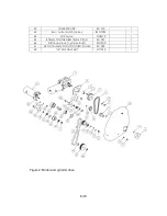
Страница 29: ...ter clutch jockey BSG1033 1 44 M12 Nyloc NNM12 1 45 800mm TOOTHED BELT 5mm PITCH EL1037 1 46 Distance piece cylinder shaft SG1000 1 47 48 TOOTH 5mm PITCH TOOTHED PULLEY EL1005 1 48 1 2 UNF HALF NUT N11020 1 Figure 2 Roller and cylinder drive ...

Страница 30: ...HER M6 WM6 4 16 Set screw M6 x 25 SM625 2 17 M8x25 COUNTER SUNK SET SCREW M6X25 CSK 2 18 C SK TOP HAT SPACER BSG1298 2 19 M8x25 COUNTER SUNK SET SCREW M8x25 CSK 2 20 TOURNAMENT FRONT ROLLER SCRAPER BSG1369 BSG1370 1 21 M6 X 12 SET SCREW SM612 2 22 SPRING WASHER M6 SWM6 4 23 20 FRONT ROLLER SHAFT BSG1321 BSG1322 1 24 GROOVED FRONT ROLLER TUBE 20 BSG1262 BSG1263 1 25 BEARING 20mm 6004 2RS AM81007 2 ...

Страница 31: ...7 19 Figure 3 Front roller assembly ...

Страница 32: ...W M8X12 BS 4168 3 M8 x 12 S 2 11 BAR REAR ROLLER LOCKING COLLAR BSG016 2 12 BEARING 20MM FLANGED AM81008 2 13 3 8 FLAT WASHER 3 8 flat washer 6 14 3 8 SPRING WASHER 3 8 spring washer 4 15 3 8 X 3 4 UNF S11011 4 16 Set screw 5 16 UNF x 3 4 ZY 2 17 M8 plain washer form G WM8G 4 18 OILITE BUSH BSG1102 2 19 PINION GEAR STEEL BSG1101 2 20 DIFFERENTIAL CARRIER BSG024 1 21 REAR ROLLER SHAFT EL1095 EL1099...

Страница 33: ...9 19 Figure 4 Rear roller drive assembly ...

Страница 34: ...245 1 18 SPACER HYDRO BOSS 32x20x3mm AFK1132 1 19 GROOMER SPACER BSG1148 46 55 20 GROOMER BLADE C1156 46 55 21 GROOMER SHAFT BSG1146 BSG1147 1 22 NARROW GROOMER SPACER BSG1223 1 23 WASHER M16 FORM C WM16C 1 24 M24 TOOTHED SHAKEPROOF WASHER WM16TI 1 25 5 8 UNF HALF NUT Z Y N11019 1 26 VERTICAL GROOMER ADJUSTER ASSY BSG082 2 27 CHAIN TENSIONER FAB MK2 TS025 1 28 SPRING CHAIN TENSIONER TS1025 1 29 CH...

Страница 35: ...HER WM8 5 46 9mm BEARING AM90513 1 47 BEARING 20mm AM81007 3 48 SMALL COMPOUND BSG025 1 49 Compound centre BSG1288 1 50 Spacer flywheel 50 x 11 2 x 5mm AFK1201 1 51 M10 NYLOC NUT NNM10 2 44 51 COMPOUND SPROCKET ASSEMBLY BSG173 1 27 29 CHAIN TENSIONER FAB MK2 TS025 1 10 11 15 25 GROOMER ASSY BSG067 BSG068 1 ...

Страница 36: ...DECAL EL1052 1 16 BACKLAP DECAL EL1053 1 17 TOP HANDLE BAR FAB RH EL008 1 18 M6X20 SET SCREW SM620 4 19 WASHER M6 WM6 14 20 NUT NYLOC M6 NNM6 6 21 TRACTION SWITCH PRESSING EL1106 1 22 HANDLE BAR CENTRE EL023 1 23 DECAL 76dB EL1055 1 24 TOP HANDLE BAR CLAMP DRILLED EL1018 2 25 SET SCREW M6 x 30 ZC SM630 6 26 SPRING WASHER M6 SWM6 14 27 A V MOUNT AM81320 4 28 SPACER FOR A V MOUNTING BSG1207 4 29 LOW...

Страница 37: ... CLAMP TAPPED EL1021 2 44 ELMOW LOOM EL1110 1 45 Fuse 4 A EL1085 2 46 M4x15 M4x15 4 47 M4 FLAT WASHER FORM A WM4 4 48 M4 NYLOC NUT NNM4 4 49 M6x15 SM615 4 50 TOP HANDLE BAR FAB LH EL007 1 17 21 22 50 TILLER HEAD ASSEMBLY EL003 1 Figure 6 Handle bar assembly ...

Страница 38: ...OCK NUT EL1073 1 13 TRIP FUSE DECAL EL1049 1 14 BATTERY ISOLATION KEY DECAL EL1050 1 15 BATTERY CONNECTION DECAL EL1046 1 16 12V 42Ah GEL BATTERY EL1066 2 17 M6X20 SET SCREW SM620 4 18 WASHER M6 FORM G ZC WM6G 4 19 M6x10 CSK M6x10 CSK 2 20 SPRING WASHER M6 SWM6 4 21 M6 X 125 CAP HEAD SCM625 2 22 WASHER M6 WM6 2 23 NUT NYLOC M6 NNM6 2 24 POSITIVE TO AMMETER CABLE EL1100 1 25 AMMETER TO ISOLATION SW...

Страница 39: ...15 19 Figure 7 Batteries and charger ...

Страница 40: ... 2 GRASSBOX STIFFENER BSG1198 BSG1199 1 3 SHAVER TOUR GRASSBOX AM81243 AM81244 1 4 SCREW FOR GRASSBOX ARM NON DRIVE SIDE C1091 4 5 3 8 FLAT WASHER W11015 4 6 NUT NYLOCK 3 8 UNF BZP N11002 4 7 ALLETT GRASSBOX DECAL AM81544 1 8 GRASSBOX ARM FAB RH BSG070 1 2 3 7 GRASSBOX ASSEMBLY COMPLETE BSG086 BSG087 1 ...

Страница 41: ...17 19 Figure 8 Grass box assembly ...

Страница 42: ...0 4 17 KICK STAND SPACER EL1040 2 18 LH WHEEL SHAFT AS1054 1 19 WHEEL HUB TS1014 2 20 NYLON BUSH TS1046 4 21 SPACER FOR WHEEL CATCH TS1045 2 22 SPRING TS1044 2 23 WHEEL CATCH TS1043 2 24 SET SCREW M8 x 25 SM825 2 25 SPIRAL BRUSH TS006 TS007 1 26 FRONT ROLLER PLAIN BSG1264 BSG1265 1 27 BEARING 20mm 6004 2RS AM81007 2 28 OIL SEAL 42 OD 26 ID 7 THK AM81524 2 29 SEAL SLEEVE AM81523 2 26 29 FRONT ROLLE...

Страница 43: ...19 19 Figure 9 Options ...

Отзывы: