
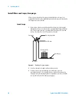


Installing the GC
1
Agilent Intuvo 9000 GC Installation
59
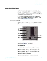
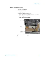
Connect the external cables.
Additional cables may be installed for control of the GC’s
automatic liquid sampler (ALS), connecting signal output to
integrators, synchronizing the start and end of a run between
various instruments, sensing conditions external to the GC, and
controlling devices external to the GC.
If using Event or BCD cables, label the cables as needed to
identify their intended use and appropriate connector on the
GC. See
.
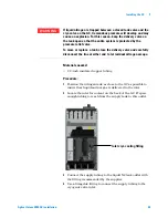
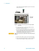
Back panel connectors
The figure below shows the connectors on the back panel of the
GC.
Sampler connectors
If using an ALS, connect it to the GC using the following
connectors:
ALS 1
Optional. An injector or 150-position sample tray.
ALS 2
Optional. An injector or 150-position sample tray.
The SIG (analog output) connectors
Optional. Use
SIG1
and
SIG2
for analog output signals.
ALS 1
ALS 2
SIG1
SIG2
REMOTE
EVENT
BCD
LAN
Содержание Intuvo 9000
Страница 1: ...Agilent Technologies Agilent Intuvo 9000 Gas Chromatograph Installation and First Startup...
Страница 6: ...6 Agilent Intuvo 9000 GC Installation...
Страница 25: ...Installing the GC 1 Agilent Intuvo 9000 GC Installation 25 3 Reinstall the GC covers...
Страница 26: ...26 Agilent Intuvo 9000 GC Installation 1 Installing the GC Connect the power cord and LAN cable LAN...
Страница 27: ...Installing the GC 1 Agilent Intuvo 9000 GC Installation 27 Turn on the GC...
Страница 29: ...Installing the GC 1 Agilent Intuvo 9000 GC Installation 29...
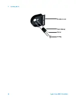
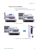
Страница 52: ...52 Agilent Intuvo 9000 GC Installation 1 Installing the GC Detector cover Vent chimney Screw O Ring...
Страница 84: ...84 Agilent Intuvo 9000 GC Installation 1 Installing the GC 8 Close the GC front door...
Страница 114: ...Agilent Technologies...


