


80
Agilent Intuvo 9000 GC Installation
1
Installing the GC
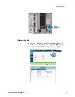
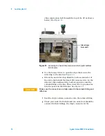
Install the checkout column
1
Use the torque driver to open the four column clamps.
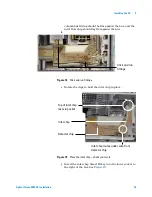
2
Place the column.
a
Place the column on the bottom clamps. (Do not tighten
the clamps yet.)
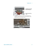
b
Tilt the column up so the click and run connectors mate
into the right-side bus fitting. Grasp the column ring as
shown in the figure and insert the column click and run
connectors into the bus fitting. The column connectors
should rest flat on top of both gasket lobes, so that the
flow chip, gasket, and column connector lobes all align
concentrically. See the figures below.
CAUTION
Hold the column assembly only by the outer ring—do not press or
pull on the column itself.
Содержание Intuvo 9000
Страница 1: ...Agilent Technologies Agilent Intuvo 9000 Gas Chromatograph Installation and First Startup...
Страница 6: ...6 Agilent Intuvo 9000 GC Installation...
Страница 25: ...Installing the GC 1 Agilent Intuvo 9000 GC Installation 25 3 Reinstall the GC covers...
Страница 26: ...26 Agilent Intuvo 9000 GC Installation 1 Installing the GC Connect the power cord and LAN cable LAN...
Страница 27: ...Installing the GC 1 Agilent Intuvo 9000 GC Installation 27 Turn on the GC...
Страница 29: ...Installing the GC 1 Agilent Intuvo 9000 GC Installation 29...
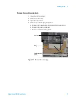
Страница 52: ...52 Agilent Intuvo 9000 GC Installation 1 Installing the GC Detector cover Vent chimney Screw O Ring...
Страница 84: ...84 Agilent Intuvo 9000 GC Installation 1 Installing the GC 8 Close the GC front door...
Страница 114: ...Agilent Technologies...


