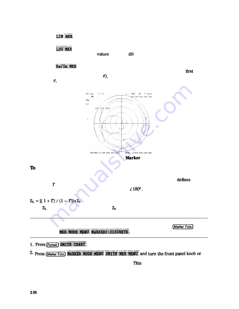
2. Select the type of polar marker you want from the following choices:
n
Choose
if you want to view the magnitude and the phase of the active marker.
The magnitude values appear in units and the phase values appear in degrees.
n
Choose
if you want to view the logarithmic magnitude and the phase of the
active marker. The magnitude
appear in and the phase values appear in
degrees.
n
Choose
if you want to view the real and imaginary pair, where the complex
data is separated into its real part and imaginary part. The analyzer shows the
marker value the real part (M cos and the second value is the imaginary part
(M sin where M=magnitude).
Figure 2-16. Example of a Log
in Polar Format
Use Smith Chart Markers
The amount of power reflected from a device is directly related to the impedance of the device
and the measuring system. Each value of the reflection coefficient (I’) uniquely
a device
impedance; = 0 only occurs when the device and analyzer impedance are exactly the same.
The reflection coefficient for a short circuit is: I’ = 1
Every other value for I’ also
corresponds uniquely to a complex device impedance, according to the equation:
where is your test device impedance and is the measuring system’s characteristic
impedance.
Note
For greater accuracy when using markers in the Smith chart format, it
is recommended to activate the discrete marker mode. Press
enter a value from the front panel keypad to read the resistive and reactive components of
the complex impedance at any point along
the
trace.
is the default Smith chart marker.
The marker annotation tells that the complex impedance is capacitive in the bottom half of
the Smith chart display and is inductive in the top half of the display.
Making Measurements
Содержание 8719D
Страница 153: ...M a k i n g M i x e r M e a s u r e m e n t s O p t i o n 089 Only1 3 19 ...
Страница 178: ...Figure 4 2 Printing Two Measurements Printing P l o t t i n g a n d S a v i n g M e a s u r e m e n t Results 4 7 ...
Страница 189: ... 4 18 Printing Plotting and Saving Measurement Results ...
Страница 338: ... Figure 6 41 Open Circuit Rmnination 6 64 Application and Operation Concepts ...
Страница 467: ......
Страница 468: ...8 2 Menu M a p s ...
Страница 469: ......
Страница 470: ...84 Menu Maps ...
Страница 473: ...Menu Maps 8 7 ...
Страница 475: ...Menu Maps a 9 ...
Страница 476: ...I 9 10 MenuYaps ...
Страница 477: ...Menu Maps 9 11 ...
Страница 478: ...MlFl EF FEFEFEII TE 9 l 2 Menu Maps ...
Страница 479: ......
Страница 480: ...8 14 Menu Maps ...
Страница 481: ...r c 1 pb6le Menu Maps 8 l 6 ...
Страница 537: ...6 66 Key Definitions ...
Страница 556: ... Ihble 9 2 Softkey Locations continued Softkey Front Panel Access Key Key Definitions 9 75 ...
Страница 557: ...9 76 Key Definitions ...
Страница 558: ...lhble 9 2 Softkey Locations continued Softkey Front Panel Access Key Key Definitions D 77 ...
Страница 559: ...Ihble 9 2 Softkey Locations continued Softkey Key Definitions ...
Страница 560: ... Jhble 9 2 Softkey Locations continued Key Definitions a 78 ...
Страница 561: ...able 9 2 Softkey Locations continued 8 80 Key Definitions ...
Страница 563: ... ble 9 2 Softkey Locations continued 842 Definitions ...
Страница 565: ...able 9 2 Softkey Locations continued Softkey Front Panel Access Key 8 64 Key Definitions ...
Страница 566: ... Ihble 9 2 Softkey Locations continued Key Definitions 8 85 ...
Страница 567: ...Kay Definitions ...
Страница 568: ... lbble 9 2 Softkey Locations continued Key Definitions 8 87 ...
Страница 569: ...lhble 9 2 Softkey Locations continued Softkey Front Panel Access Key 8 88 KeyDefinitions ...
Страница 570: ... able 9 2 Softkey Locations continued Softkey Front Panel Access Key Key Definitions 8 88 ...
Страница 571: ...840 Key Definitions Ihble 9 2 Softkey Locations continued Softkey Front Panel Access Key ...
Страница 572: ...able 9 2 Softkey Locations continued Softkey Front Panel Key Definitions 8 81 ...
Страница 573: ... Ihble 9 2 Softkey Locations continued Softkey Front Panel Access Key 842 Key Definitions ...


