background image

52


Chapter 3: Testing Performance

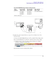
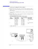
To test the multiple-clock state acquisition

b

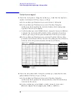
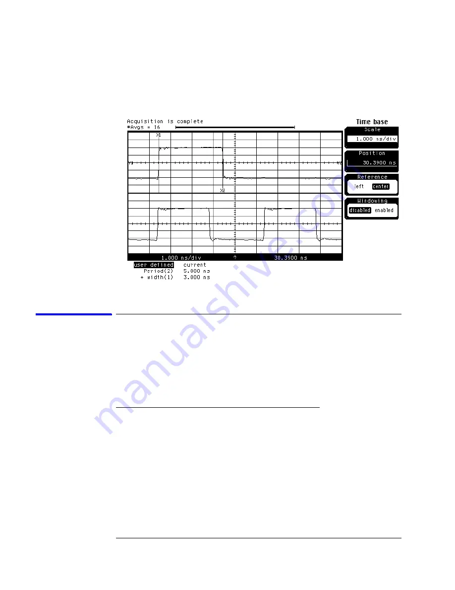
On the oscilloscope, select [Shift] + width: channel 1, then select 
[Enter] to display the data signal pulse width (+ width (1)).

c

If the pulse width is outside the limits, adjust the pulse generator 
channel 2 width until the pulse width is within limits.

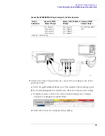
Check the setup/hold with single clock edges, multiple 
clocks

The following setup/hold combinations will be tested.

Setup/Hold Combinations

1

Disable the pulse generator channel 1 COMP (LED off).

2

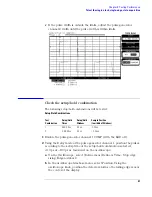
Using the Delay mode of the pulse generator channel 1, position the pulses 
according to the setup time of the setup/hold combination selected, 
+0.0 ps or 

100 ps as measured on the oscilloscope:

a

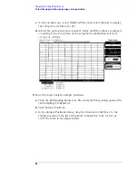
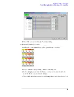
On the Oscilloscope, select [Define meas] Define 

 Time - Stop edge: 

rising, Edge number 2. 

Test
Combination

Setup/Hold
Times

Setup/Hold
Window

Sample Position
(in middle of Window)

1

5.0/-2.0 ns

3.0 ns

-3.5 ns

2

-1.5/4.50 ns

3.0 ns

+3.0 ns

Содержание 1680 series

Страница 1: ...umber 01680 97016 October 2005 For Safety information Warranties and Regulatory information see the pages at the end of the book Copyright Agilent Technologies 2001 2004 2005 All Rights Reserved Advan...

Страница 2: ...erfaces IEEE 1394 interface for hosted control Variable setup hold time 512K acquisition memory in the Agilent 1680A series 2M acquisition memory in the Agilent 1680AD series Marker Measurements PS 2...

Страница 3: ...ding a defective assembly by testing and servicing the Agilent 1680 90 series logic analyzers This logic analyzer can be returned to Agilent for all service work including troubleshooting Contact your...

Страница 4: ...er for use Chapter 3 gives instructions on how to test the performance of the logic analyzer Chapter 4 contains calibration instructions for the logic analyzer Chapter 5 contains self tests and flowch...

Страница 5: ...17 To connect the 1690A AD series logic analyzer to a host PC 17 To start the user interface 18 To clean the logic analyzer 18 To test the logic analyzer 18 3 Testing Performance The Logic Analyzer In...

Страница 6: ...cquisition 48 Set up the equipment 48 Connect and configure the logic analyzer 49 Verify the test signal 51 Check the setup hold with single clock edges multiple clocks 52 Test the next channels 1680...

Страница 7: ...6 To test the logic analyzer probe cables 107 To check the BNC Trigger input output signals 110 To test the auxiliary power 112 6 Replacing Assemblies 1680A AD series disassembly assembly 114 Prepare...

Страница 8: ...ts List 145 Exploded View 146 Agilent 1680A AD Series Replaceable Parts 147 Exploded View 153 Agilent 1690A AD Series Replaceable Parts 154 Power Cables and Plug Configurations 157 8 Theory of Operati...

Страница 9: ...9 1 General Information This chapter lists the accessories the specifications and characteristics and the recommended test equipment...

Страница 10: ...de but further upgrades may change the part number Do not be concerned if the accessory you receive has a different part number Accessories Available For probing information see Probing Solutions for...

Страница 11: ...justable in 100 ps increments Single Clock Multiple Edges 5 0 2 0 ns through 1 5 4 5 ns adjustable in 100 ps increments Multiple Clocks Multiple Edges 5 0 2 0 ns through 1 5 4 5 ns adjustable in 100 p...

Страница 12: ...ad sets and cables 0 C to 65 C 32 F to 149 F Disk media 10 C to 40 C 50 F to 104 F Humidity Instrument probe lead sets and cables up to 80 relative humidity at 40 C 122 F Altitude To 3067 m 10 000 ft...

Страница 13: ...13 Chapter 1 General Information Dimensions 1680A AD Series 1690A AD Series...

Страница 14: ...P BNC Banana Cable 11001 60001 P BNC Tee BNC m f f 1250 0781 P Cable BNC m m 48 inch 8120 1840 P T SMA Coax Cable Qty 3 18 GHz bandwidth 8120 4948 P Adapter Qty 4 SMA m BNC f 1250 1200 P T Adapter SM...

Страница 15: ...15 2 Preparing for Use This chapter gives you instructions for preparing the logic analyzer for use...

Страница 16: ...noncondensing Note the recommended noncondensing humidity Condensation within the instrument can cause poor operation or malfunction Provide protection against internal condensation Storage Store or...

Страница 17: ...te AC power outlet this cable grounds the instrument cabinet The type of power cable plug shipped with the instrument depends on the country of destination Refer to chapter 7 Replaceable Parts for opt...

Страница 18: ...al for a brief explanation of the Agilent Logic Analyzer standard icons To clean the logic analyzer With the instrument turned off and unplugged use mild soap and water to clean the front and cabinet...

Страница 19: ...19 3 Testing Performance This chapter tells you how to test the performance of the logic analyzer against the specifications listed in chapter 1...

Страница 20: ...on page 3 8 are each shown from power up To exactly duplicate the setups in the tests save the power up configuration to a file on a disk then load that file at the start of each test If a test fails...

Страница 21: ...the Berg strip b Solder a jumper wire to all pins on the other side of the Berg strip c Solder two resistors to the Berg strip one at each end between the end pins d Solder the center of the BNC conne...

Страница 22: ...Build one test connector using a BNC connector and a 17 by 2 section of Berg strip a Solder a jumper wire to all pins on one side of the Berg strip b Solder a jumper wire to all pins on the other side...

Страница 23: ...able above Let them warm up for 30 minutes before beginning any test 2 Set up the pulse generator according to the following table Pulse Generator Setup 3 Set up the oscilloscope a Select Setup then s...

Страница 24: ...r panel of the logic analyzer b Plug in a power cord to the rear panel power connector of the logic analyzer c Turn on the power switch on the logic analyzer front panel 2 Set up the logic analyzer a...

Страница 25: ...nalyzer icon to launch the application c In the Agilent Logic Analyzer application window ensure the application reports Online To perform the logic analyzer self tests The Self Test menu checks the m...

Страница 26: ...ted tests repetitively until you click Stop Stop on fail if you are running multiple tests or running tests repetitively this causes the tests to stop if there is a failure Double click item to start...

Страница 27: ...t To view the log file click Logs select the log file you want to view and click Open If after completing the self tests you have failures or you have questions about the performance of the logic anal...

Страница 28: ...r Equipment Required Set up the equipment 1 If you have not already done so do the procedure To set up the test equipment and the logic analyzer on page 23 2 Set up the DC source to deliver a DC volta...

Страница 29: ...ree side of the BNC Tee 2 Configure the logic analyzer a Click the Bus Signal Setup icon The Analyzer Setup dialog opens b In the Buses Signals tab click Delete All at the bottom of the dialog c Using...

Страница 30: ...d Settings dialog d Click OK to close the Analyzer Setup dialog 2 Test the high to low transition a On the DC source enter a voltage setting of 1 384 V b On the logic analyzer click the Run icon The d...

Страница 31: ...in the associated field d Click OK to close the Threshold Settings dialog e Click OK to close the Analyzer Setup dialog 2 Test the high to low transition a On the DC source enter a voltage setting of...

Страница 32: ...the 17 by 2 test connector and probe tip assembly connect the data and clock channels of the next pod to the output of the function generator until all pods have been tested 2 Start with Connect and...

Страница 33: ...nalyzer application to reinitialize the logic analyzer 2 Configure the Analyzer Setup dialog a Click the Sampling Setup icon b Select State Synchronous Sampling c Configure Trigger Position 100 postst...

Страница 34: ...icon d For the Default Storage select Store Nothing e Click OK to close the Advanced Trigger dialog 4 Activate the pulse generator data and clock outputs a On the pulse generator enable the channel 1...

Страница 35: ...ue d Click on the Occurs button and the Value dialog appears e Click on the Find occurrences field and enter 4096 f Click on the pattern field then enter the following pattern according to the logic a...

Страница 36: ...erties dialog select Beginning Of Data in the from field The logic analyzer markers are now configured to verify the test data If the error message can t find 4096 occurence s does not appear the test...

Страница 37: ...ng procedures To set up the test equipment and the logic analyzer on page 23 To set up the logic analyzer for the state mode tests on page 33 Connect and configure the logic analyzer 1 Using the 6 by...

Страница 38: ...esting Combinations Connect to 8133A Channel 2 Output Connect to 8133A Channel 2 Output Connect to 8133A Channel 1 Output 1 Pod 1 channel 3 Pod 3 channel 3 Pod 5 channel 3 Pod 7 channel 3 Pod 2 channe...

Страница 39: ...uses Signals tab click Delete All at the bottom of the dialog c Using the mouse activate the data channels being tested Assign channels to bus signal name My Bus 1 d Click OK to close the Analyzer Set...

Страница 40: ...r to display the clock period Period 2 If the period is not less than 5 000 ns go to step d If the period is less than 5 000 ns go to step 2 d In the oscilloscope Timebase menu increase Position 5 000...

Страница 41: ...2 Using the Delay mode of the pulse generator channel 1 position the pulses according to the setup time of the setup hold combination selected 0 0 ps or 100 ps as measured on the oscilloscope a On th...

Страница 42: ...es are aligned according to the setup time of the setup hold combination selected 0 0 ps or 100 ps 3 Select the logic analyzer sample positions a Click the Sampling Setup icon The Analyzer Setup dialo...

Страница 43: ...o close the Sample Positions dialog 4 Select the clock to be tested The following clock configurations will be used in steps 4 5 and 6 a In the Analyzer Setup dialog click on the Sampling tab b In the...

Страница 44: ...ogrammed into the Markers If the test passes record a Pass in the performance test record under single clock single edge next to the clock and edge being tested 6 Test the next clock a Click on the Sa...

Страница 45: ...elay until the pulses are aligned according to the setup time of the setup hold combination selected 0 0 ps or 100 ps 9 Select the clock to be tested The following clock configurations will be used in...

Страница 46: ...he test passes when the logic analyzer finds all occurances of the patterns programmed into the Markers If the test passes record a Pass in the performance test record under single clock single edge n...

Страница 47: ...acquisition Test the next channels 1680 81A AD and 1690 91A AD Connect the next combination of data channels and clock channels then test them Start with Connect and configure the logic analyzer on p...

Страница 48: ...d times Equipment Required Set up the equipment 1 If you have not already done so do the following procedures To set up the test equipment and the logic analyzer on page 23 To set up the logic analyze...

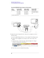
Страница 49: ...scilloscope to the pulse generator Connect the 1680 81 90 91A AD Logic Analyzer to the Pulse Generator Testing Combinations Connect to 8133A Channel 2 Output Connect to 8133A Channel 2 Output Connect...

Страница 50: ...k Delete All at the bottom of the dialog c Using the mouse activate the data channels being tested Assign channels to bus signal name My Bus 1 d Click OK to close the Analyzer Setup dialog Testing Com...

Страница 51: ...elect Shift Period channel 2 then select Enter to display the clock period Period 2 If the period is not less than 5 000 ns go to step d If the period is less than 5 000 ns go to step 2 d In the oscil...

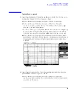
Страница 52: ...multiple clocks The following setup hold combinations will be tested Setup Hold Combinations 1 Disable the pulse generator channel 1 COMP LED off 2 Using the Delay mode of the pulse generator channel...

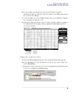
Страница 53: ...r to display the setup time Time 1 2 d Adjust the pulse generator channel 1 Delay until the pulses are aligned according to the setup time of the setup hold combination selected 0 0 ps or 100 ps 3 Sel...

Страница 54: ...r for My Bus 1 to the sample position of the first setup hold combination to be tested or enter the value in the signal fields d Click OK to close the Sample Positions dialog 5 Verify the test data a...

Страница 55: ...ling b On the oscilloscope select Shift Time Select Start src channel 1 then select Enter to display the setup time Time 1 2 c Adjust the pulse generator channel 1 Delay until the pulses are aligned a...

Страница 56: ...lock single edge next to the clock and edge being tested 10 Test the next setup hold combination a Click the Bus Signal Setup icon b Disconnect the clock just tested from the pulse generator c Repeat...

Страница 57: ...nt Required Set up the equipment 1 If you have not already done so do the following procedures To set up the test equipment and the logic analyzer on page 23 To set up the logic analyzer for the state...

Страница 58: ...channel 1 channel 2 and trigger from the oscilloscope to the pulse generator Connect the 1680 81 90 91A AD Logic Analyzer to the Pulse Generator Testing Combinations Connect to 8133A Channel 2 Output...

Страница 59: ...Buses Signals tab click Delete All at the bottom of the dialog c Using the mouse activate the data channels being tested Assign channels to bus signal name My Bus 1 d Click OK to close the Analyzer S...

Страница 60: ...t a rising edge appears at the left of the display d On the oscilloscope select Shift width channel 2 then select Enter to display the master to master clock time width 2 If the positive going pulse w...

Страница 61: ...m so that the waveform is centered on the screen c On the oscilloscope select Shift width channel 1 then select Enter to display the data signal pulse width width 1 d If the pulse width is outside the...

Страница 62: ...t is near the center of the display c On the oscilloscope select Shift Time Select Start src channel 1 then select Enter to display the setup time Time 1 2 d Adjust the pulse generator channel 2 Delay...

Страница 63: ...g 3 Select the clock to be tested The following clock configurations will be used in steps 3 4 and 5 a In the Analyzer Setup dialog click the Sampling tab b In the Sampling tab click the Master button...

Страница 64: ...nds all occurrences of the patterns programmed into the Markers If the test passes record a Pass in the performance test record under single clock single edge next to the clock and edge being tested 5...

Страница 65: ...ition Test the next channels 1680 81A AD and 1690 91A AD Connect the next combination of data channels and clock channels then repeat the previous test Start with Connect and configure the logic analy...

Страница 66: ...the test equipment and the logic analyzer on page 23 b Exit and restart the Agilent Logic Analyzer applications to reinitialize the logic analyzer 2 Set up the pulse generator according to the follow...

Страница 67: ...tor channel 1 output 2 Using the SMA cable and the BNC adapter connect the External Input of the pulse generator to the Main Signal of the function generator 3 Enable the function generator output and...

Страница 68: ...lete All at the bottom of the dialog b Using the mouse select Pod 1 channel 0 to activate the channel c Click the threshold field for Pod 1 In the Threshold Settings dialog select Standard and ECL 1 3...

Страница 69: ...Click the Run icon to fill acquisition memory 2 Set up the M1 marker for time interval measurement a From the main menu choose Markers Properties b In the Marker Properties tab of the Waveform Proper...

Страница 70: ...read Value Occurs from M1 g Click Apply then click OK to close the Waveform Properties dialog 4 An Interval Measurement should already be visible in the Markers Toolbar If not choose Markers New Time...

Страница 71: ...Fail ________ Threshold Accuracy 65 mV 1 5 of threshold setting Pod 1 ECL 84 mV 0 V 65 mV Pass Fail Pass Fail ________ ________ Pod 2 ECL 84mV 0 V 65mV Pass Fail Pass Fail ________ ________ Pod 3 ECL...

Страница 72: ...1 Clk 2 Clk 3 Clk 4 ________ ________ ________ ________ Clk 1 Clk 2 Clk 3 Clk 4 ________ ________ ________ ________ Setup Hold Time 2 0 4 5 ns Clk 1 Clk 2 Clk 3 Clk 4 ________ ________ ________ ______...

Страница 73: ...old Time 5 0 2 0 ns Clk 1 Clk 2 Clk 3 Clk 4 _______ _______ _______ _______ Setup Hold Time 1 5 4 5 ns Clk 1 Clk 2 Clk 3 Clk 4 _______ _______ _______ _______ All Pods Channel 11 Setup Hold Time 5 0 2...

Страница 74: ...74 Chapter 3 Testing Performance Performance Test Record...

Страница 75: ...75 4 Calibrating and Adjusting This chapter gives you instructions for calibrating and adjusting the logic analyzer...

Страница 76: ...alibration The logic analyzer circuitry of the Agilent 1680 90 series logic analyzers does not require an operational accuracy calibration To test the logic analyzer circuitry against specifications f...

Страница 77: ...77 5 Troubleshooting This chapter helps you troubleshoot the logic analyzer to find defective assemblies...

Страница 78: ...ies logic analyzer they must be first uninstalled and removed before doing any troubleshooting Removing user installed hardware or software will rule out the possibility they are causing problems and...

Страница 79: ...cedure to remove the fan guard and reassemble the instrument To use the flowcharts Flowcharts are the primary tool used to isolate defective assemblies The flowcharts refer to other tests to help isol...

Страница 80: ...he Agilent Logic Analyzer application software Is the problem still present Do the self test Refer to Chapter 5 Yes No Replace the acquisition board No Do the self tests pass Yes No Yes Is the applica...

Страница 81: ...power supply Perform To test the power supply voltages in Chapter 5 Do all test points pass Ensure all instrument cables are connected and properly seated Replace the power supply Yes No Yes No Yes No...

Страница 82: ...rm To test the fan voltage in Chapter 5 Replace the defective fan Are both instrument fans stopped Suspect the power supply Perform To test the power supply voltages in Chapter 5 Do all test points pa...

Страница 83: ...No Yes Yes Are all cables connected and seated Reconnect or reseat all video cabling Replace the LCD display and inverter Replace PCI video board with known good board Ensure PCI video board is seated...

Страница 84: ...operating system logon screen appear Yes Yes Reinstall operating system See To recover the operating system Is logon disabled No No No Does starting Windows appear No Does error message refer to hard...

Страница 85: ...ll cables connected and seated Reconnect or reseat all internal cabling Possible problem with acquisition board Replace acquisition bd Reseat the PCI IEEE board in ISA slot 1 Apply power to the instru...

Страница 86: ...suspect pod Does cable test pass Swap suspect probe tip assembly with known good one Does cable test pass Swap suspect cable assembly with known good one Does cable test pass Replace logic analyzer ac...

Страница 87: ...nitor the boot dialogue When the text Starting Windows appears at the bottom of the screen this means required system components have been detected and have passed their power up self tests To test th...

Страница 88: ...power cord to the power supply and plug the power cord into line power 5 Using DVM measure the power supply voltages Power Supply Voltages 6 Note problems with the power supply then unplug the power...

Страница 89: ...ated Refer to chapter 6 Replacing Assemblies for instructions to remove or replace covers and assemblies WARNING Warning Hazardous voltages exist on the power supply and the LCD display and the LCD in...

Страница 90: ...help further identify possible problems with either the flexible disk drive or hard disk drive Equipment Required 1 Close the Agilent Logic Analyzer application and all other applications running on...

Страница 91: ...ed booting launch the Agilent Logic Analyzer application c Insert a formatted flexible disk in the instrument flexible disk drive d Attempt to do a File Save of the Agilent Logic Analyzer default conf...

Страница 92: ...assemble the instrument To verify the CD ROM The CD ROM drive itself can be tested using an audio CD Install CD player style headphones in the CD ROM audio output jack With the instrument powered on i...

Страница 93: ...t CD ROM drive If the instrument finishes booting then user files can likely be archived so they don t become lost 3 Press the on off button to turn the instrument off 4 After a few seconds turn the i...

Страница 94: ...ppear consult the operating system documentation for information related to the errors In case the whole system becomes unresponsive turn the instrument off by pressing the on off button If pressing t...

Страница 95: ...ilent Logic Analyzer application software on the host PC Is the problem still present Do the self test Refer to Chapter 5 Yes No Replace the acquisition board No Do the self tests pass Yes No Yes Is t...

Страница 96: ...Suspect the power supply Perform To test the power supply voltages in Chapter 5 Do all test points pass Ensure all instrument cables are connected and properly seated Replace the power supply Yes No Y...

Страница 97: ...n the acquisition board Is connectivity verified Uninstall then reinstall the Agilent Logic Analyzer application Uninstall then reinstall the Agilent Logic Analyzer application Does the application so...

Страница 98: ...suspect pod Does cable test pass Swap suspect probe tip assembly with known good one Does cable test pass Swap suspect cable assembly with known good one Does cable test pass Replace logic analyzer ac...

Страница 99: ...ction with the 1690A AD series hosted logic analyzer when the logic analyzer is connected to the PC If the agLogicSvc service is not listed then the host PC will not be able to establish an interface...

Страница 100: ...onal operating system Consult the documentation for the operating system to determine why the device is not being installed and run To test the power supply voltages Refer to chapter 6 Replacing Assem...

Страница 101: ...emove the power supply from the instrument Refer to To remove the power supply in Chapter 6 4 After removing the poser supply connect a power cord to the power supply and plug the power cord into line...

Страница 102: ...102 Chapter 5 Troubleshooting Troubleshooting the Agilent 1690A AD series 6 Note problems with the power supply then unplug the power supply from line power Return to flow chart...

Страница 103: ...Chapter 8 for more information on the logic analyzer self tests CAUTION Because the most recently acquired data will be lost be sure to save important data before running self tests 1 Do the following...

Страница 104: ...itively until you click Stop Stop on fail if you are running multiple tests or running tests repetitively this causes the tests to stop if there is a failure Double click item to start lets you double...

Страница 105: ...llowing results should be reported in the status window To stop a running test click Stop To reset the self test options click Reset To view the log file click Logs select the log file you want to vie...

Страница 106: ...of the interface FPGA in the acquisition board When the Red LED is on and steady this indicates the FPGA configuration software has not been successfully loaded into the FPGA Failure to load the FPGA...

Страница 107: ...agLogicSvc service then loads configuration code into the interface FPGA on the acquisition board When the FPGA is configured the red LED is turned off The acquisition board is then properly configur...

Страница 108: ...he pulse generator channel 1 OUTPUT c Connect the even numbered channels of the upper byte of the pod under test to the pulse generator channel 2 OUTPUT d Connect the odd numbered channels of the uppe...

Страница 109: ...the mouse activate all channels for the pod under test Assign channels to bus signal name My Bus 1 d Click on the threshold field for the pod under test The Threshold Settings dialog appears e In the...

Страница 110: ...pen channel Channel shortened to a neighboring channel Channel shortened to either ground or a supply voltage Return to Troubleshooting flowchart 7 To check the BNC Trigger input output signals 1 Turn...

Страница 111: ...the event to trigger on c Then select External trigger as the source of the arming signal d Click OK to close the Advanced Trigger dialog 5 Verify the external trigger a Select the Run icon The logic...

Страница 112: ...39 exceed 0 33 amps the circuit will open When the short is removed the circuit will reset in approximately 1 minute There should be 5 V after the 1 minute reset time Equipment Required Use the multim...

Страница 113: ...113 6 Replacing Assemblies This chapter contains the instructions for removing and replacing the assemblies of the logic analyzer Also in this chapter are instructions for returning assemblies...

Страница 114: ...t already done so do the previous procedure Prepare the instrument for disassembly 1 Using a Torx T 15 screwdriver remove the two screws that secure the handle to the side of the instrument and lift...

Страница 115: ...properly so the sleeve does not cause any damage to the cables To remove the acquisition board 1 Do the procedure To remove the chassis from the sleeve 2 Turn the chassis upside down 3 Disconnect the...

Страница 116: ...hex screwdriver remove two hex nuts from the acquisition board trigger BNC connectors 8 Using a Torx T 10 screwdriver remove five screws that secure the probe shroud to the acquisition board Reverse t...

Страница 117: ...from the sleeve 2 Disconnect the 16 pin power supply cable and the power sense cable from the distribution board 3 Using a Torx T 15 screwdriver remove four screws that secure the power supply to the...

Страница 118: ...ommet to the replacement power supply as shown To remove the hard disk drive 1 Do the procedure To remove the chassis from the sleeve 2 Using a Torx T 15 screwdriver remove four screws that secure the...

Страница 119: ...er remove five screws that secure the CD ROM drive assembly to the chassis 5 Slide the CD ROM assembly out of the chassis Remove the CD ROM from the assembly 1 1 Using a Torx T 10 screwdriver remove t...

Страница 120: ...ket Lift the CD ROM drive out of the bottom bracket 5 Reverse this procedure to reassemble and install the CD ROM drive Ensure the motherboard is properly installed before installing the CD ROM drive...

Страница 121: ...drive to the chassis 4 Slide the flexible disk drive out the rear of the front panel and out of the chassis 5 Reverse this procedure to install the flexible disk drive When installing a new flexible d...

Страница 122: ...leeve 2 Disconnect the cable from the board to be removed PCI IEEE 1394 board IEEE 1394 cable PCI display board video cable 3 Using a Torx T 10 screwdriver remove one screw that secures each PCI board...

Страница 123: ...peripheral boards from the motherboard using the procedure To remove the PCI boards 4 Disconnect the following cables from the motherboard power switch cable from motherboard J1 pins 6 and 8 hard dis...

Страница 124: ...d to the chassis 7 Reverse this procedure to install the motherboard If the motherboard requires replacing then do the following steps Transfer the I O panel to the replacement board 1 Using a 3 16 in...

Страница 125: ...t is installed as follows a Two 80 mm sections are installed one on each side of the top center screw hole b One 160 mm section is installed centered along the bottom edge of the I O panel directly be...

Страница 126: ...the tie wrap off the on off cable 3 Disconnect the display cable from the PCI display board 4 Disconnect the following cables from the distribution board on off cable accessed from the bottom of the...

Страница 127: ...panel assembly After installing the front panel assembly onto the chassis loop the on off cable and dress the cable with a cable tie Agilent part number 1400 0249 or similar Dressing the cable with a...

Страница 128: ...omeric keypad out of the front panel Remove the LCD display 1 Using a Torx T 10 screwdriver remove four screws one in each corner that secures the LCD display to the front panel 2 Lift the LCD display...

Страница 129: ...ered and applied refer to chapter 7 for the part number To remove the distribution board 1 1 Do the following procedures To remove the chassis from the sleeve To remove the front panel assembly 2 Disc...

Страница 130: ...d To remove the inverter board 1 Do the procedure To remove the chassis from the sleeve 2 Disconnect both the inverter input and inverter LCD inverter output cables from the inverter board 3 Using a T...

Страница 131: ...leeve 2 Disconnect the fan cables from the distribution board 3 Using needle nosed pliers remove the plastic push fastener insert from the push fasteners securing one of the fans to the chassis 4 Dise...

Страница 132: ...nd applied to the cable tray depending on the 1680A AD series instrument the cable tray is installed on 1680A AD 01680 94307 1681A AD 01680 94308 1682A AD 01680 94309 1683A AD 01680 94310 1 Remove the...

Страница 133: ...d placed in a static safe work environment If you haven t already done so do the previous procedure Prepare the instrument for disassembly 1 Using a Torx T 15 screwdriver remove the two screws that se...

Страница 134: ...installing the chassis into the sleeve ensure all exposed cables are dressed properly so the sleeve does not cause any damage to the cables To remove the fascia 1 Do the procedure To remove the chass...

Страница 135: ...e part number Also Pod labels 01680 94313 must be ordered and applied in the same way as on the fascia being replaced Steps to remove the on off switch from the fascia assembly 1 Using a Torx T 10 scr...

Страница 136: ...he logic analyzer front panel 4 Slide the acquisition board out of the logic analyzer front panel Steps to remove the probe shroud from the acquisition board 1 Using a hex screwdriver remove two hex n...

Страница 137: ...from the chassis To remove the power supply 1 Do the following procedures To remove the chassis from the sleeve To remove the front panel assembly To remove the deck 2 Disconnect the power supply out...

Страница 138: ...r supply on off cable to the replacement power supply To remove the distribution board 1 Do the following procedures To remove the chassis from the sleeve To remove the front panel assembly To remove...

Страница 139: ...Do the procedure To remove the chassis from the sleeve 2 Disconnect the fan cables from the distribution board and remove the cables from the cable clips 3 Using needle nosed pliers remove the plasti...

Страница 140: ...o the following procedures To remove the chassis from the sleeve To remove the front panel assembly To remove the deck 2 Disconnect the power supply line input cable from the power supply 3 Using a To...

Страница 141: ...e the acquisition board 2 Remove the trim strips from the top and sides of the front frame 3 Using a Torx T 15 screwdriver remove four screws that secure the top of the front panel to the front frame...

Страница 142: ...142 Chapter 6 Replacing Assemblies 1690A AD series disassembly assembly...

Страница 143: ...143 7 Replaceable Parts This chapter contains information for identifying and ordering replaceable parts for your logic analyzer...

Страница 144: ...s Sales Office Within the USA Agilent Technologies can supply parts through a direct mail order system The advantages to the system are direct ordering and shipment from the Agilent Technologies Part...

Страница 145: ...een a new assembly and that of the exchange assembly For orders not originating in the United States contact your nearest Agilent Technologies Sales Office for information See Also To return assemblie...

Страница 146: ...146 Chapter 7 Replaceable Parts Exploded View Exploded view of the Agilent 1680A AD series logic analyzer...

Страница 147: ...Channel x 2 Mbit 1680AD A2 01680 66508 1 Acquisition Board 34 Channel x 2 Mbit 1693AD A2 01680 66509 1 Acquisition Board 68 Channel x 2 Mbit 1692AD A2 01680 66510 1 Acquisition Board 102 Channel x 2 M...

Страница 148: ...o chassis probe shroud to chassis PCI board and ISA slot covers to chassis CD ROM drive assembly to chassis sleeve to chassis H4 0515 0433 12 M4 0 x 0 70 8 mm T20 PH power supply to chassis cable tray...

Страница 149: ...sis MP12 01680 68701 1 Probe Shroud MP13 01680 68702 1 Accessory Pouch MP14 01680 68707 1 Handle Assembly MP15 01680 68708 1 Sleeve Assembly MP16 01680 87102 1 EMI Gasket I O panel to chassis MP17 016...

Страница 150: ...able to chassis MP34 54810 61001 4 Bottom Foot MP35 8160 1545 0 65 EMI Gasket I O panel to chassis CD ROM assembly to chassis W1 01680 61604 1 PC Power Cable distribution board to motherboard W2 01680...

Страница 151: ...el circuit board to front frame LCD display to front frame H12 0515 1934 2 M2 5 x 0 45 6 mm T8 PH power switch interface board to front frame MP36 01680 01702 1 Module Cover MP37 01680 41901 1 On Off...

Страница 152: ...CD to LCD display MP42 54801 47401 3 Knob 12 MM Flint Gray MP43 54801 47402 3 Knob 18 MM Gray W16 01680 61602 1 Display Cable W17 01680 61603 1 On Off Cable W18 01680 61611 1 Calibration Cable W19 016...

Страница 153: ...153 Chapter 7 Replaceable Parts Exploded View Exploded view of the Agilent 1690A AD series logic analyzer...

Страница 154: ...rd 34 Channel x 2 Mbit 1693AD A1 01680 66509 1 Acquisition Board 68 Channel x 2 Mbit 1692AD A1 01680 69510 1 Acquisition Board 102 Channel x 2 Mbit 1691AD A1 01680 69517 1 Acquisition Board 34 Channel...

Страница 155: ...0 PH probe cable to probe shroud 1692A AD H6 0515 2306 2 M3 0 x 0 5 10 mm T10 PH probe cable to probe shroud 1693A AD H7 54503 25701 2 Hex Nut acquisition board BNC connectors to probe shroud MP1 0166...

Страница 156: ...4 Snap accessory pouch to sleeve MP18 1400 1254 3 Cable Clip 0 5 in diameter 0 75 in wide PVC fan cables to chassis on off cable to chassis MP19 16600 49301 2 Molded Plastic Bumper MP20 16600 68707 1...

Страница 157: ...a Zimbabwe Singapore Opt 901 250V 8120 0696 90 87 221 Mint Gray Australia New Zealand Opt 902 250V 8120 1692 90 79 200 Mint Gray East and West Europe SaudiArabia So Africa India unpolarized in many na...

Страница 158: ...8120 8871 90 Thailand Part number shown for plug is industry identifier for plug only Number shown for cable is Agilent Technologies part number for complete cable including plug These cords are inclu...

Страница 159: ...159 8 Theory of Operation This chapter tells the theory of operation for the logic analyzer and describes the self tests...

Страница 160: ...d what the self tests are testing This information is not intended for component level repair Block Level Theory The block level theory is divided into two parts theory for the logic analyzer and theo...

Страница 161: ...k Drives The Agilent 1680A AD series logic analyzer contains a 3 5 hard disk drive as well as a 3 5 micro flexible disk drive Flat Panel Display The Agilent 1680A AD series logic analyzer includes an...

Страница 162: ...board where they are filtered and distributed to other boards and components in the system Acquisition Board Logic Acquisition Board Block Diagram Probing The probing system consists of a tip network...

Страница 163: ...ogic analyzer board for a total of up to 128 data channels and four state clock pods one through four in state mode There are 136 data channels available in timing mode All of the sequencing store qua...

Страница 164: ...through this interface All state and timing functions including storage qualification sequencing assigning clocks and qualifiers RUN and STOP and thresholds are controlled in the manner A microcontro...

Страница 165: ...he unit is connected to AC power The standby rail powers the microcontoller and some core circuitry on the front panel board The remaining circuitry on the front panel board is powered by the main 5V...

Страница 166: ...erate the logic analyzer acquisition board The power supply also provides the 5V VDC voltage to the probe cables to power the logic analyzer accessories and analysis probes Unfiltered voltages of 12V...

Страница 167: ...ation about parametric performance verification Power up Self Tests 1680A AD series The power up self tests on the 1680A AD series logic analyzers is performed by the Microsoft Windows 2000 Profession...

Страница 168: ...t to the memory port of each acquisition memory IC and stored The data in the acquisition memory ICs are then downloaded and compared with known values Passing the Memory Test implies the acquisition...

Страница 169: ...s Test The Memory Modes Test verifies the CPU interface can properly manage the acquisition memory unload in full channel half channel count only and interleaved modes Test data is written to acquisit...

Страница 170: ...gnal is routed to a test port on each comparator The threshold is then set to the minimum value The comparator output is then read and compared with a known value The threshold is then set to a maximu...

Страница 171: ...fferent unload modes are selected then the data is read and compared with known values Passing the Memory Modes Test implies that the data can be reliably read from acquisition memory in full channel...

Страница 172: ...172 Chapter 8 Theory of Operation Self Tests Descriptions...

Страница 173: ...only in accordance with the terms of such license Restricted Rights Legend If software is for use in the performance of a U S Govern ment prime contract or sub contract Softwareisdelivered and license...

Страница 174: ......
Отзывы: