39
Chapter 3: Testing Performance
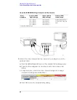
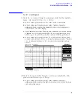
To test the single-clock, single-edge, state acquisition
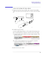
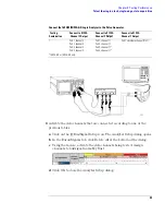
Connect the 1682/83/92/93A,AD Logic Analyzer to the Pulse Generator
3
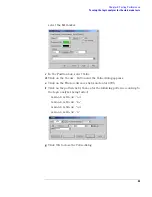
Activate the data channels that are connected according to one of the
previous tables:
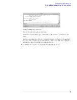
a
Click on the
Bus/Signal Setup icon. The Analyzer Setup dialog opens.
b
In the Buses/Signals tab, click Delete All at the bottom of the dialog.
c
Using the mouse, activate the data channels being tested. Assign
channels to bus/signal name My Bus 1.
d
Click OK to close the Analyzer Setup dialog.
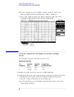
Testing
Combination
Connect to 8133A
Channel 2 Output
Connect to 8133A
Channel 2 Output
Connect to 8133A
Channel 1 Output
1
Pod 1, channel 3
Pod 2, channel 3
Pod 3, channel 3
Pod 4, channel 3
Pod 1, channel 11
Pod 2, channel 11
Pod 3, channel 11*
Pod 4, channel 11*
Pod 1 clock/data channel (Clk 1)
*1682A,AD or 1692A,AD only.
Содержание 1680 series
Страница 13: ...13 Chapter 1 General Information Dimensions 1680A AD Series 1690A AD Series...
Страница 15: ...15 2 Preparing for Use This chapter gives you instructions for preparing the logic analyzer for use...
Страница 74: ...74 Chapter 3 Testing Performance Performance Test Record...
Страница 77: ...77 5 Troubleshooting This chapter helps you troubleshoot the logic analyzer to find defective assemblies...
Страница 142: ...142 Chapter 6 Replacing Assemblies 1690A AD series disassembly assembly...
Страница 146: ...146 Chapter 7 Replaceable Parts Exploded View Exploded view of the Agilent 1680A AD series logic analyzer...
Страница 153: ...153 Chapter 7 Replaceable Parts Exploded View Exploded view of the Agilent 1690A AD series logic analyzer...
Страница 159: ...159 8 Theory of Operation This chapter tells the theory of operation for the logic analyzer and describes the self tests...
Страница 172: ...172 Chapter 8 Theory of Operation Self Tests Descriptions...
Страница 174: ......

