24
Precautions for use and maintenance
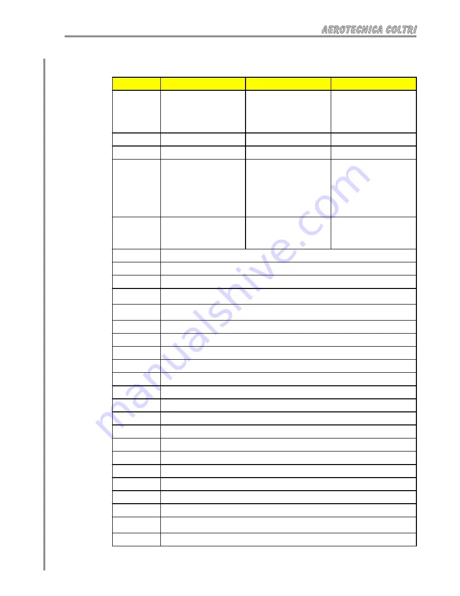
POSITION
SAFETY DEVICE
DESCRIPTION
INSPECTION
1
Safety valves.
Protect the third stage and the cylinders
fro m b ei ng o ve rfille d ; it is ca lib ra te d
during the inspection of the compres-
sors.
The safety valve must b e checked at
e a c h f i lli ng o p e ra t i o n; s ta r t up t he
co mp re ss or with the cyli nd e r va lve s
closed and the filling cock open. Check
tha t the safety valve sta rts op era ting
correctly with the pres-sure gauge, open
the valves and proceed with the filling.
2
Sound-proofed frame.
Built of steel.
Periodically check its integrity.
3
Side panels.
Fixed with locks.
Periodically check their integrity.
4
Ma nua l co nd e nsa te d i sc ha rg e ta p s
(auto ma tic fo r a ll mod els e xcep t the
Standard models).
T h e c o n d e n s a t e i s a m i l k y - w h i t e
emulsion formed of oil and water.
The a b so rptio n o f wa te r b y the fi lter
c a us e s we a r o n the fi lte r i ts e lf a nd
consequent contamination.
Open the discharge taps every 10-15
minutes and make sure the condensate
comes out visibly and consistently.
If the condensate is discharged automa-
tically, check that it operates correctly by
opening the manual discharge taps. The
condensate should be present in mini-
mum quantities.
5
A ctivated carbon filter and mo lecular
sieve.
The quality of the air depends to a great
extent on the conditions of the filter and
sieve.
The cartridge must be replaced before
the air becomes foul smelling.
For the frequency of replacement, see
the instructions in C hapter 11, "Main-
tenance".
6
Electrical switcboard built to EN 60204-1 regulations with IP 54 level of protection and fitted with a lock and key.
7
8
Pressure gauge showing the operating pressure.
9
Pressure switch that can be manually calibrated showing the maximum cylinder filling pressure; when the set pressure is reached,
the compressor turns off.
10
Sealed hour counter to memorize the actual hours of operation in order to be able to carry out the maintenance procedures at
the proper intervals.
11
Danger of crushing hands symbol (if the side panels are removed).
12
Danger of moving parts symbol.
13
Danger of voltage present symbol.
14
Removal of safety devices prohibited symbol.
15
Work on moving parts prohibited symbol.
16
Smoking prohibited symbol.
17
Gloves compulsory picture diagram.
18
Goggles compulsory picture diagram.
19
Helmet compulsory picture diagram.
20
Rating plate on the electric motor giving data concerning voltage, phases, frequency, breaking capacity.
21
Pump unit oil level indicator.
22
Machine plate showing the CE mark.
23
Hose area : danger of direct contact by the operator if breakage should occur during cylinder filling.
24
Voltage warning plate. Only qualified staff may intervene.
25
Warning sign presence of oxygen - DANGER OF EXPLOSION
(see "Safety Regu-
lations" enclosed)
Warning to use the machine and carry out maintenance in accordance with the instruction manual.
(see chapter 11)
Warning to cut off the power supply before carrying out any maintenance work.
Table 1
Содержание MCH 14 TECH NITROX SERIES
Страница 31: ...31 Installation 3 Pass the pipe through the hole located in the rear guard Fig 29 30 28 29 ...
Страница 80: ...80 Troubleshooting 12 1 1 Low pressure compressor ...
Страница 85: ...85 Compression diagram High pressure compressor only air Machine diagrams 14 2 ...
Страница 86: ...86 Machine diagrams 14 3 Electrical diagram ...
Страница 87: ...87 Machine diagrams ...
Страница 100: ...100 153 152 156 155 154 158 097 157 159 160 198 188 187 189 Filtering system High pressure compressor Spare parts ...
Страница 104: ...104 Pulley Crankcase and cylinder Low pressure compressor Spare parts ...
Страница 105: ...105 Piston rod unit Low pressure compressor Spare parts ...
Страница 106: ...106 Cylinder Valve and Filter unit Low pressure compressor Spare parts ...
Страница 107: ...107 Pump unit Low pressure compressor Spare parts ...


