I
GB
THINGS YOU SHOULD KNOW
To avoid overheating of the electric motor, this compressor is designed for intermittent operation as indicated
on the dataplate (for example, S3-50 means 5 minutes ON and 5 minutes OFF). In the case of overheating,
the thermal cutout of the motor trips, automatically cutting off the power when the temperature is too high
due to excess current take-off
.
On
single-phase
versions, press the reset button on the terminal box of the motor
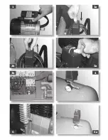
(fig. 1).
To facilitate machine restart, it is important not only to carry out
the operations indicated
but also to set the button of the
pressure switch, returning this to the OFF position and then ON again
(figures 2a - 2b)
.
On
3-phase
versions, operate manually on the button of the pressure switch, returning this to the ON position or press the
button of the thermal cutout inside the box of the electric panel
(figures 3a - 3b)
.
The single-phase versions are fitted with a pressure switch equipped with a delayed closing air vent valve (or with a valve
located on the check valve) that facilitates motor start-up; therefore a few-second jet of air from this, with the reservoir
empty, is to be considered normal.
To guarantee machine safety, all the compressors are fitted with a safety valve that is activated in the case of failure of the
pressure switch.
(fig. 4)
.
All two-stage compressors are equipped with safety valves on the air delivery manifold to the reservoir and on the connection
hose between the low and high pressure located on the head. These are activated in the case of malfunctioning
(fig. 5)
.
When connecting an air-powered tool to a hose of compressed air supplied by the compressor, interruption of the flow of air
from the hose is compulsory.
Use of the compressed air for the various purposes envisaged (inflation, air-powered tools, painting, washing with water-
based detergents only, etc.) requires knowledge of and compliance with the rules established for each individual use.
START-UP AND USE
Fit the wheels and foot (or the caster wheel for models that are fitted with this) according to the instructions provided in the
packaging. For versions with fixed feet, assemble the front bracket kit or the vibration-dampers if furnished. Check that the
rating data match the effective characteristics of the system (voltage and power).
Insert the power plug in a suitable socket checking that the button of the pressure switch located on the compressor is in the
“O” (OFF) position
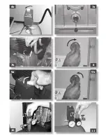
(figures 6a - 6b)
.
For the 3-phase versions, connect the plug to a panel protected by suitable fuses.
For the versions fitted with electric panel (“Tandem” control units or delta/star starters) have installation and connections (to
the motor, to the pressure switch and to the electrovalve if any) carried out by qualified personnel.
Check the oil level using the sight glass and if necessary unscrew the vent plug and top up. (
figures 7a - 7b)
.
At this point, the compressor is ready for use.
Operating on the switch of the pressure switch (or the selector for versions with electric panel, (
figures 6a – 6b - 8
), the
compressor starts, pumping air in the reservoir through the delivery hose. On 2-stage versions, air is sucked in to the so-
called low pressure cylinder liner and precompressed. It is then routed, through the recirculation hose, into the so-called high
pressure liner and then into the reservoir. With this work cycle, it is possible to reach higher pressure, with availability of air
at 11 bar (15 bar for special machines).
On reaching maximum operating pressure (factory-set during testing), the compressor stops, venting the excess air present
in the head and in the delivery hose through a valve located under the pressure switch (in delta/star versions, through an
electrovalve that is activated when the motor stops).
The absence of pressure in the head facilitates subsequent restart. When air is used, the compressor
restarts automatically when the lower calibration value is reached (approx. 2 bar between upper and lower).
The pressure inside the reservoir can be checked on the gauge provided
(fig. 4)
.
The compressor continues to operate automatically with this work cycle until the position of the switch of the pressure switch
(or of the selector of the electric panel)
figures 2a – 9a – 9b)
is modified.
To use the compressor again, wait at least 10 seconds after this has been switched off before restarting.
In the versions with electric panel, the pressure switch must always be aligned with the I (ON) position.
In tandem versions, the control unit provided permits use of only one of the two compressor groups (if necessary alternatively)
or of both at the same time according to requirements. In this second case, start-up will be differentiated slightly to avoid
excessively high current take-off at start-up (timed starting).
Only the wheel-mounted compressors are fitted with a pressure reducer (in the versions with fixed feet, it is usually installed
on the use line). Air pressure can be regulated in order to optimize use of air-powered tools operating on the knob with the
valve open (pulling it up and turning it in a clockwise direction to increase pressure and counterclockwise to reduce this) (
fig.
10
). Once you have set the value required, push the knob down to lock it.
Содержание 556182 - 62
Страница 2: ...3b 2a 1 2b 3a 6a 4 5 ...
Страница 3: ...7a 7b 8 6b 9b 9a 11 10 ...
Страница 4: ...12 15 13 14a 14b 17 16 18a ...
Страница 5: ...20b 21 19 18b 20c 20a ...


