Signal Connections
25
3.2
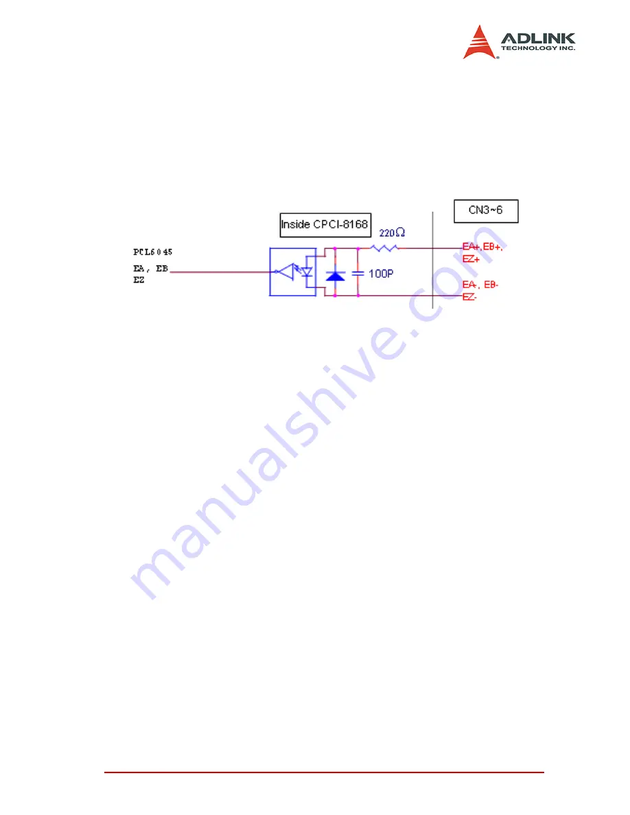
Encoder Feedback Signals EA, EB and EZ
The encoder feedback signals include the EA, EB, and EZ. Every
axis has six pins for three differential pairs of phase-A (EA),
phase-B (EB) and index (EZ) input. The EA and EB are used for
position counting, the EZ is used for zero position index. The input
circuits of the EA, EB, EZ signals are shown as follows.
Please note that the voltage across every differential pair of
encoder input signals (EA+, EA-), (EB+, EB-) and (EZ+, EZ-)
should be at least 3.5V or higher. Therefore, you have to take
care of the driving capability when connecting with the encoder
feedback or motor driver feedback. The differential signal pairs
will be converted to digital signal EA, EB and EZ to connect to
PCL6045 ASIC.
Here are two examples of connecting the input signals with the
external circuits. The input circuits can connect to the encoder or
motor driver, which are equipped with: (1) differential line driver or
(2) open collector output.
3.2.1
Connection to Line Driver Output
To drive the cPCI-8168 encoder input, the driver output must pro-
vide at least 3.5V across the differential pairs with at least 6 mA
driving capability. The ground level of the two sides must be tight
together.
Содержание cPCI-8168
Страница 4: ......
Страница 10: ...vi List of Figures...
Страница 29: ...Installation 19 2 9 Overview of CN3 CN6...
Страница 31: ...Installation 21 2 11 Switch Setting...
Страница 124: ...114 Function Library Src Counter source Return Code ERR_NoError Value Meaning 0 External Feedback 1 Command pulse...
Страница 134: ...124 Function Library Return Code ERR_NoError ERR_SpeedError ERR_PChangeSlowDownPointError ERR_MoveRatioError...
Страница 155: ...Function Library 145 12 At FH speed maximum velocity 13 In deceleration 14 Waiting for INP signal 15 Reserved...
Страница 204: ...194 Function Library...


