Page 4-4
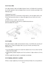
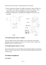
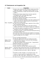
Follow the following steps to re-align tailstock to the spindle.
1)
Insert a gauge bar between the spindle and tailstock, attach the base of a
test indicator to the saddle, and apply the stylus of the indicator to the
surface of the bar, of its maximal difference for later adjustment.
2)
Release the fixing screw 1 and adjust the adjusting screw 2 to fine the
alignment.
4.2.4
4.2.5
4.2.5 Adjusting belt tension of spindle
The main spindle torque which depends on the motor power transmitted
through the belt, the operator must check the V belt’s tension frequently by
adjusting screw if it becomes loosen.
4.2.6 Adjusting belt tension of x-axis
The new belt tension of X-axis should be 2.9mm elastic length when pressed by
1kg force. After a period of time, if the belt turned looser, adjust the belt to be
2.9mm by 1kg.
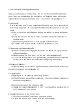
4.3 Electric equipment
4.3.1 Motor
Содержание ATL 1820E
Страница 5: ...1 SAFETY INSTRUCTIONS ...
Страница 22: ...Page 1 17 ...
Страница 24: ...2 MACHINE SPECIFICATIONS ...
Страница 25: ...Page 2 1 2 MACHINE SPECIFICATIONS 2 1 Dimensional drawing ...
Страница 27: ...Page 2 3 2 1 2 Chip Conveyor ...
Страница 31: ...3 INSTALLATION ...
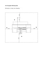
Страница 34: ...3 1 2 Layout floor plan Following is a top view drawing ...
Страница 43: ...4 MAINTENANCE ...
Страница 55: ...5 CHUCK ...
Страница 64: ...Page 7 3 7 1 HEADSTOCK 1 HEADSTOCK _ 18 SPINDLE BORE 58mm 2 ...
Страница 65: ...Page 7 4 18 SPINDLE BORE 58mm 2 ...
Страница 69: ...Page 7 8 7 2 BED Z AXIS TRANSMISSION ...
Страница 71: ...Page 7 10 7 3 CARRIAGE CROSS SLIDE ...
Страница 74: ...Page 7 13 7 4 TAILSTOCK MANUAL TAILSTOCK _ 18 ...

