Page 1-6
1.3.1 Wiring
1)
Be sure to use electrical conductors with performance ratings equivalent or
superior to those described in the Maintenance Manual.
2)
Do nut connect to the power distribution panel any power cables for device,
which can cause Line noise, such as, are welders and high frequency
quenching machines.
3)
Arrange for a qualified engineer to connect the power lines.
1.3.2 Grounding
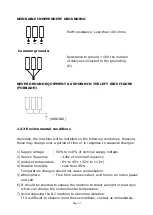
Use a grounding wire with a cross section of more than 14 mm and a resistance
to ground of less Than 100 ohms.
This wire size should be greater than AWB (American Wire Gauge) No. 5 and
SWG (British Legal Standard Wire Gauge) No.6.
Generally, the NC machine should be ground to a separate grounding rod. If an
independent ground cannot be provided for the machine, prepare the ground
connection as follow:
1)
Connect a single conductor to its grounding terminal. This will avoid possible
serious accidents resulting from ground currents, which might otherwise
flow in the NC machine if a peripheral device, should malfunction.
2)
Be careful when using concrete reinforcing rods as grounding points. These
reinforcing rods often are used to ground equipment because they usually
offer a resistance to ground of less than 100 ohms. In doing so, make the
connections as follow:
A.
Do not use the same grounding-reinforcing rod or grounding terminal for
other devices since this could lead to line noise such as produced electric
welders and high frequency quenching machine.
B.
Use a grounding terminal with an adequate electrical performance rating
and which is durable.
3)
A separate grounding wire should be used, one whose length is as short as
possible.
4)
Check the resistance to ground by actual measurement. This should
measure less than 100 ohms if the single device is connected to its own
grounding rod.
Содержание ATL 1820E
Страница 5: ...1 SAFETY INSTRUCTIONS ...
Страница 22: ...Page 1 17 ...
Страница 24: ...2 MACHINE SPECIFICATIONS ...
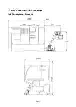
Страница 25: ...Page 2 1 2 MACHINE SPECIFICATIONS 2 1 Dimensional drawing ...
Страница 27: ...Page 2 3 2 1 2 Chip Conveyor ...
Страница 31: ...3 INSTALLATION ...
Страница 34: ...3 1 2 Layout floor plan Following is a top view drawing ...
Страница 43: ...4 MAINTENANCE ...
Страница 55: ...5 CHUCK ...
Страница 64: ...Page 7 3 7 1 HEADSTOCK 1 HEADSTOCK _ 18 SPINDLE BORE 58mm 2 ...
Страница 65: ...Page 7 4 18 SPINDLE BORE 58mm 2 ...
Страница 69: ...Page 7 8 7 2 BED Z AXIS TRANSMISSION ...
Страница 71: ...Page 7 10 7 3 CARRIAGE CROSS SLIDE ...
Страница 74: ...Page 7 13 7 4 TAILSTOCK MANUAL TAILSTOCK _ 18 ...

