


197
A
AFLASH Utility
33
Antennas
Removing
94, 96
Replacing
98
B
Battery
Replacing
135
Battery Pack
Removing
47
BIOS
ROM type
16
vendor
16
BIOS Utility
25–33
Advanced
28
Boot
31
Exit
32
Navigating
25
Onboard Device Configuration
29
Power
31
Save and Exit
32
Security
28
System Security
32
Board Layout
Top View
155
brightness
hotkeys
13
C
Camera Module
Removing
89
Replacing
101, 103, 104, 106
Common Problems
138
computer
on indicator
9
CPU
Removing
83
Replacing
109
D
DIMM Modules
Replacing
130
Display
5
display
hotkeys
13
E
EasyTouch Failure
148
External Module Disassembly
Flowchart
46
F
Features
1
Flash Utility
33
FPC Cable
Removing
91
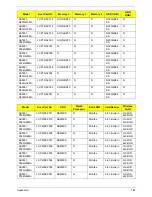
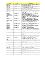
FRU (Field Replaceable Unit) List
161
H
Hard Disk Drive
Removing
56
Replacing
128
HDTV Switch Failure
149
Hibernation mode
hotkey
13
Hot Keys
11
I
Indicators
9
Intermittent Problems
150
Internal Microphone Failure
143
Internal Speaker Failure
142
J
Jumper and Connector Locations
155
K
Keyboard
Removing
59
Replacing
127
Keyboard Failure
141
L
LCD Bezel
Replacing
105
Index
Содержание ASPIRE 5251
Страница 6: ...VI...
Страница 10: ...X Table of Contents...
Страница 34: ...24 Chapter 1...
Страница 52: ...42 Chapter 2...
Страница 72: ...62 Chapter 3 3 Turn the computer over and disconnect the following four 4 cables from the Mainboard A B C D...
Страница 76: ...66 Chapter 3 5 Lift the Speaker clear of the Upper Cover...
Страница 78: ...68 Chapter 3 5 Lift the Right Speaker Module clear of the device...
Страница 84: ...74 Chapter 3 5 Lift the USB board clear of the device...
Страница 90: ...80 Chapter 3 11 Disconnect the Bluetooth to mainboard cable...
Страница 92: ...82 Chapter 3 4 Carefully lift the Thermal Module clear of the Mainboard...
Страница 103: ...Chapter 3 93 7 Disconnect the LVDS cable from the panel...
Страница 105: ...Chapter 3 95 5 Lift the microphone set and cable clear of the LCD cover...
Страница 114: ...104 Chapter 3 Replacing the Camera Module 1 Place the Camera in the module 2 Connect the camera cable...
Страница 121: ...Chapter 3 111 5 Connect the fan cable...
Страница 124: ...114 Chapter 3 6 Connect the LVDS cable to the mainboard 7 Connect the microphone cable...
Страница 127: ...Chapter 3 117 4 Connect the USB cable to the mainboard and lock the connector...
Страница 130: ...120 Chapter 3 4 Replace the FFC and press down as indicated to secure it to the Upper Cover...
Страница 135: ...Chapter 3 125 3 Connect the following cables to the Mainboard 4 Connect D as shown 5 Connect C as shown A B C D...
Страница 146: ...136 Chapter 3...
Страница 173: ...Chapter 6 163 Base Assembly No Description Acer P N 1 Logic Lower Door 2 3G Door 3 Lower Cover 1 2 3...
Страница 175: ...Chapter 6 165 Aspire 5251 5551G 5551 FRU List...
Страница 176: ...166 Chapter 6 Screw List...
Страница 177: ...Chapter 6 167...
Страница 206: ...196 Appendix C...
Страница 210: ...200...


