


110
Chapter 3
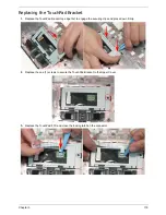
Replacing the Thermal Module
IMPORTANT:
Apply a suitable thermal grease and ensure all heat pads are in place before replacing the Thermal
Module.
The following thermal grease types are approved for use:
•
N-302 Dimand TIM Grease
•
Honeywell
The following thermal pads are approved for use:
•
Eapus XR-PE
1.
Remove all traces of thermal grease from the CPU using a lint-free cloth or cotton swab and Isopropyl
Alcohol, Acetone (1), or other approved cleaning agent.
2.
Apply a small amount of thermal grease to the centre of the CPU—there is no need to spread the grease
manually, the force used during the installation of the Thermal Module is sufficient.
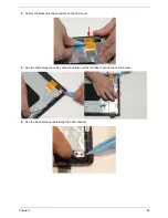
3.
Align the screw holes on the Thermal Module and Mainboard then replace the module. Keep the module as
level as possible to spread the thermal grease evenly.
4.
Replace the four (4) securing screws (in reverse numerical order from screw 4 to 1), then the two (2) screws
on the GPU.
1
2
3
4
Содержание ASPIRE 5251
Страница 6: ...VI...
Страница 10: ...X Table of Contents...
Страница 34: ...24 Chapter 1...
Страница 52: ...42 Chapter 2...
Страница 72: ...62 Chapter 3 3 Turn the computer over and disconnect the following four 4 cables from the Mainboard A B C D...
Страница 76: ...66 Chapter 3 5 Lift the Speaker clear of the Upper Cover...
Страница 78: ...68 Chapter 3 5 Lift the Right Speaker Module clear of the device...
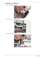
Страница 84: ...74 Chapter 3 5 Lift the USB board clear of the device...
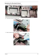
Страница 90: ...80 Chapter 3 11 Disconnect the Bluetooth to mainboard cable...
Страница 92: ...82 Chapter 3 4 Carefully lift the Thermal Module clear of the Mainboard...
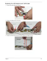
Страница 103: ...Chapter 3 93 7 Disconnect the LVDS cable from the panel...
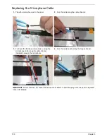
Страница 105: ...Chapter 3 95 5 Lift the microphone set and cable clear of the LCD cover...
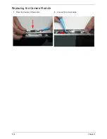
Страница 114: ...104 Chapter 3 Replacing the Camera Module 1 Place the Camera in the module 2 Connect the camera cable...
Страница 121: ...Chapter 3 111 5 Connect the fan cable...
Страница 124: ...114 Chapter 3 6 Connect the LVDS cable to the mainboard 7 Connect the microphone cable...
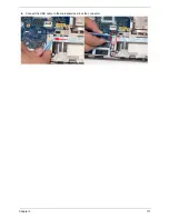
Страница 127: ...Chapter 3 117 4 Connect the USB cable to the mainboard and lock the connector...
Страница 130: ...120 Chapter 3 4 Replace the FFC and press down as indicated to secure it to the Upper Cover...
Страница 135: ...Chapter 3 125 3 Connect the following cables to the Mainboard 4 Connect D as shown 5 Connect C as shown A B C D...
Страница 146: ...136 Chapter 3...
Страница 173: ...Chapter 6 163 Base Assembly No Description Acer P N 1 Logic Lower Door 2 3G Door 3 Lower Cover 1 2 3...
Страница 175: ...Chapter 6 165 Aspire 5251 5551G 5551 FRU List...
Страница 176: ...166 Chapter 6 Screw List...
Страница 177: ...Chapter 6 167...
Страница 206: ...196 Appendix C...
Страница 210: ...200...


