


46
Chapter 3
External Module Disassembly Process
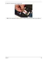
IMPORTANT:
The outside housing and color may vary from the mass produced model.
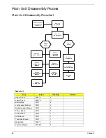
External Modules Disassembly Flowchart
The flowchart below gives you a graphic representation of the external module disassembly sequence and
instructs you on the components that need to be removed during servicing. For example, if you want to remove
the keyboard, you must first remove the switch board.
Screw List
Step
Screw
Quantity
Part No.
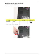
ODD Module
M 2.5*8
1
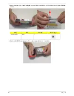
ODD Bracket
M2*3
2
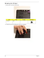
3G Cover
M2*3
1
Logic Lower Door
M2.5*8
2
WLAN Module
M2*3
1
HDD Carrier
M3*3
4
Disconnect power
and signal cables
from system
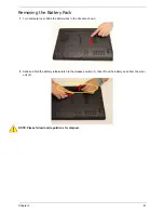
Remove
Battery
Turn off system
and peripherals
power
Remove
DIMMs
Remove
WLAN
Remove
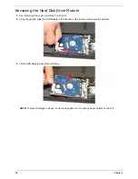
HDD
Remove
ODD
Remove
HDD/WLAN/DIMM
Door
Remove
Dummy Card
Remove
3G Cover
Содержание ASPIRE 5251
Страница 6: ...VI...
Страница 10: ...X Table of Contents...
Страница 34: ...24 Chapter 1...
Страница 52: ...42 Chapter 2...
Страница 72: ...62 Chapter 3 3 Turn the computer over and disconnect the following four 4 cables from the Mainboard A B C D...
Страница 76: ...66 Chapter 3 5 Lift the Speaker clear of the Upper Cover...
Страница 78: ...68 Chapter 3 5 Lift the Right Speaker Module clear of the device...
Страница 84: ...74 Chapter 3 5 Lift the USB board clear of the device...
Страница 90: ...80 Chapter 3 11 Disconnect the Bluetooth to mainboard cable...
Страница 92: ...82 Chapter 3 4 Carefully lift the Thermal Module clear of the Mainboard...
Страница 103: ...Chapter 3 93 7 Disconnect the LVDS cable from the panel...
Страница 105: ...Chapter 3 95 5 Lift the microphone set and cable clear of the LCD cover...
Страница 114: ...104 Chapter 3 Replacing the Camera Module 1 Place the Camera in the module 2 Connect the camera cable...
Страница 121: ...Chapter 3 111 5 Connect the fan cable...
Страница 124: ...114 Chapter 3 6 Connect the LVDS cable to the mainboard 7 Connect the microphone cable...
Страница 127: ...Chapter 3 117 4 Connect the USB cable to the mainboard and lock the connector...
Страница 130: ...120 Chapter 3 4 Replace the FFC and press down as indicated to secure it to the Upper Cover...
Страница 135: ...Chapter 3 125 3 Connect the following cables to the Mainboard 4 Connect D as shown 5 Connect C as shown A B C D...
Страница 146: ...136 Chapter 3...
Страница 173: ...Chapter 6 163 Base Assembly No Description Acer P N 1 Logic Lower Door 2 3G Door 3 Lower Cover 1 2 3...
Страница 175: ...Chapter 6 165 Aspire 5251 5551G 5551 FRU List...
Страница 176: ...166 Chapter 6 Screw List...
Страница 177: ...Chapter 6 167...
Страница 206: ...196 Appendix C...
Страница 210: ...200...


